GPS Fundamentals
[GNSS(global navigation satellite system)]
agilent-gps fundamentals.pdf
GPS(USA)=1575MHz, Glonass(Russia)=1602MHz,
Galileo(EU)=1575MHz, Compass(China)=1590MHz, QZSS(Japan)
[GPS Signal Format]

[GPS Signal Mathematics]
lu-GPS signal level.pdf
GPS �˵�: ��ǥ��� 20,200km
Received power at the Earth's surface: –130dBm with 0dBic antenna
SV EIRP 13.4dBW
Free-space loss (25,092km) -184.4dB
Attmospheric attenuation -2.0dB
User antenna gain(hemispherical) 3.0dB
Depolarizatio loss -3.4dB
-----------------------------------------------------------
User receiver power -160dBW
= -130dBm
Thermal noise power per Hz -174dBm/Hz
User receiver C/N0 ratio 44dBHz
without receiver noise
Typical average received power -125dBm
High-sensitivity receiver -158
to -152dBm
 (bilich-gps receiver SNR.pdf)
 (maccougan-hsgps.pdf)
GPS receiver sensivity:
langley-gps receiver noise.pdf
Shannon-Hartley
theorem: in Gaussian noise environment
![]()
C: channel capacity = data rate = bps
B: channel's passband bandwidth
N: total noise power in the bandwidth B
Example: spread-spectrum communication. C = 12.2kbps, B = 5MHz �� S/N = –27.7 dB, S/N << 1, ![]() (N0: white noise)
(N0: white noise)
Nyquist rate: ![]() (number of pulses per second)
(number of pulses per second)
CNR: at pre-detection in the RF stage. Used to check the health of
the RF channel
SNR: at pre-modulation or post-detection
Signal-to-noise ratio unit: C/N (or S/N) depend on the
bandwidth of the receiver's tracking loop, which is not necessarily constant
nor publicly available. Thus, the C/N or S/N is scaled by the receiver to the
standard bandwidth of 1Hz, which results in bandwidth-independent C/N0
or S/N0 measured in dBHz units.
GPS receiver sensitivity:
Acquisition
sensitivity: -140 to -150dBm
Tracking
sensitivity: -150 to -160dBm
Sensitivity formulas:
1) ![]() (simple
estimator)
(simple
estimator)
C/N0 = 174-130-2 = 42dB
2)
![]()
Ps = -130dBm
kT0 = -171dBm/Hz
I0 = power density of the interfering signal per Hz
C/N0 = ���� dB-Hz. open sky 40-50dB-Hz, ������ 15-40dB-Hz, �dz� 25dB-Hz ����.
System
noise temperature:
![]() (receiver thermal noise), k = 1.38��10-38 W/(K��Hz)
(Boltzman's constant)
(receiver thermal noise), k = 1.38��10-38 W/(K��Hz)
(Boltzman's constant)
![]()
Ta = 130 K, �� = 0.91, NF =
1.5 dB, Tsys = 263 K
N (at the antenna input) = –174 dBm/Hz
C/N0
= –130��–(–174) = 44 dB
GPS
antenna noise:
![]()
Tant = antenna noise temp.
��: antenna cable loss (fractional)
Ta: antenna noise temperature w/o cable loss. 130 K (typ.)
3)
Received power at the Earth's surface: –130dBm with 0dBic antenna
C/N0 = 44dBHz
with a 0 dBc gain antenna. A common commercial GPS receiver can acquire the GPS
signal above 38 dBHz.
C/A code band width: 4MHz, N
= -108dBm
S/N = –22dB
Indoor attenuation: 15-30dB. Low SNR requires a longer acquisition
time.
Processing gain = 10 log (chip rate/data rate) = 43 dB, chip rate =
1.023 Mcps, data rate = 50 bps
Post-correlator Eb/N0 = 9.5 dB for BPSK with BER
= 10‑5 (AWGN dominated). Eb
= energy per bit
Post-correlator Eb/N0 = processing gain �� SNR
Pre-correlator SNR = post-correlator Eb/N0
– processing gain (dB) = –33.5 dB
Software GPS implementation loss = 3.5 dB
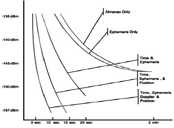
SV Acquisition
time vs signal level:
[GPS
Receiver Architecture]
GPS signals are
acquired and tracked by hardware and software techniques that vary considerably
from receiver to receiver.
Modern
receivers are largely digital in design and used software-based digital signal
processing techniques often with 12 or more parallel channel receivers.
Almanac: used
in a receiver to determine SVs visible and the Doppler shift for each SV. Valid
for 3 months.
Ephemeris: used
to calculate the precise position of each SV. Valid for 4 hours.
Ionospheric
model: transmitted every 12.5 min.
GPS-UTC time
correction parameters: transmitted every 12.5 min.
First SV acquired
�� Calibrate the receiver oscillator �� Reduce search space for subsequent SV
searches.
• Front-end
|
|
LNA |
SAW |
Coax |
RF |
Mixer |
IF |
NF(total) |
|
G(dB) |
28 |
-1.5 |
-3.9 |
19 |
-6 |
19 |
|
|
NF(dB) |
0.8 |
1.5 |
3.9 |
3.3 |
6 |
7 |
1 |
High-sensitivity receiver:
maccougan-hsgps.pdf
In
high-sensitivity receivers, massive parallel correlation is necessary to
facilitate the complex task of searching for weak GPS signals while using long coherent
integration periods and further non-coherent accumulation.
 (diggelen-a-gps.pdf)
 (maccougan-hsgps.pdf)
 (diggelen-a-gps.pdf)
High-sensitivity
GPS receiver architecture
 (diggelen-a-gps.pdf)
Coherent and
non-coherent integration:
 (diggelen-a-gps.pdf)
Coherent
integration: sequential correlation of multiple 1ms sequences (N times). Signal voltage increase by a
factor of N while the noise (uncorrelated and not band-limited) voltage
increases by a factor of N1/2.
The gain by a coherent integration is given by
![]()
Every 20ms
there is a possible navigation bit transition that can change the phase of the
correlation peak. This 20ms period limits coherent integration of the GPS
signal unless the navigation bits are known a-priori. In addition, any residual
frequency error after Doppler removal can cause the power in the in-phase
component to increase such that there is no point in further integration. In
other words, coherent integration is very sensitive to frequency error.
Non-coherent
integration uses the square root of the sum of squares of the in-phase and
quadrature phase signal components after coherent correlation of some interval.

I3, Q3 = the accumulated
in-phase/quadrature-phase coherent signal after correlation.
M = number of incoherent accumulations
Navigation bits
become irrelevant in the non-coherent integration and some residual frequency
errors during non-coherent accumulation that are within the carrier tracking
bandwidth of the receiver can be tolerated. However, squaring of the signal in
non-coherent accumulation also results in squaring of the noise and results in
squaring loss.
The squaring
loss is significant if the post coherent correlation SNR is low. Thus, maximal
coherent integration prior to non-coherent integration results in less squaring
loss.
The total
processing gain is given by
![]()
The limitations
of coherent accumulation are data bit transitions and residual frequency
errors. Predicting the data bit transitions and limiting residual frequency
errors during coherent correlation is necessary to obtain optimal gain prior to
non-coherent accumulation. This is because reduction of the resulting squaring
loss is paramount to beneficial non-coherent accumulation. The limitations of
coherent correlation are highly dependent on the receiver operating mode. If
the receiver is already tracking the GPS signals, the task of maintaining
signal tracking under weak signal conditions is much easier than acquisition of
weak GPS signals.
For weak signal
acquisition
- Maximize the
coherent integration interval prior to non-coherent accumulation.
- Minimize
residual frequency errors during coherent integration: oscillator instability,
user-motion induced Doppler effects, thermal noise inducing frequency error
jitter. Thermal noise can often be a dominant source of carrier tracking error,
especially for weak GPS signal tracking.
- Minimize the
impact of the thermal noise.
The amount of
tolerable frequency error during the total dwell time depends on the length of
coherent integration and the type of carrier tracking performed. A frequency
lock loop and/or a phase lock loop are used to perform Doppler removal.
- Minimize the
signal loss in the signal chain.
 (maccougan-hsgps.pdf)
Receiver architectures:
[Commercial GPS Receivers]
• Common:
update rate 1-20Hz, dynamic = 4g, 515m/s, 18km altitude; 55mW power tracking.
0.9dB NF 20dB gain LNA, 1.2dB Rx chip NF, SBAS(WAAS/EGNOS) support, 7-day
extended ephemeris AGPS, multipath detection and mitigation, Jamming detection
and mitigation
• Sensitivity =
-148dBm(cold start), -165dBm (tracking), �ҿ�ð��� ������� ������ ������ �� �ִ� �ּ� ��ȣ ����
• TTFF spec.:
with 0dBic antenna.
• SkyTraQ(US)
Venus628LP: single-chip 7x7mm, 65-ch., 8M time-freq search/sec (8MIPS), 2.5m
CEP, TTFF(open sky) = 29s(cold), 1s(hot), 3.5s AGPS; Re-acq. < 1s
•
Falcom(Germany) USB-GPS-Stick: u-blox UBX-G5010 single chip (u-blox 5 engine),
50-ch., high sen. for indoor fix., extremely fast TTFF at low signal levels,
Galileo capable, A-GPS support, integrated TCXO, CMC antenna, 1M effective
correlator, TTFF less than 1s with long correlation/dwell times, 4Hz update;
TTFF= 29s(cold), 29s(warm), <1s(hot); sensitivity = -144dBm(acq.),
-160dBm(track), antenna peak gain -1dBic
• US Technology
UST-SNR-GPS: 18x18mm ceramic antenna w/o larger ground plane, -1dBic max. gain,
MTK MT3318 chipset, 50-ch.; DPGS RTCM protocol WAAS, EGNOS, MSAS; 3m CEP; TTFF
= 36s(cold), 33s(warm), 1s(hot), <1s(reacq.); sensitivity = -146dBm(cold),
-158dBm(track), -158dBm(reacq.)
• SiRF star III: Digital and RF in a single chip, 200,000+ effective
correlator, 12-ch, L1 C/A code, 10Hz update,
- Reference signal level: open
sky = all SV > -144dBm, indoor = 7 SV's at -155dBm, 1 SV at -147dBm
- AGPS by CDMA: open sky <
1s, indoor < 18s
- Hot start: open sky < 1s,
indoor <15s
- Cold start: open sky < 35s
- Tracking sensitivity -159dBm
- Position accuracy: <10m
autonomous, <5m SBAS
SiRF III with 21*13*4 chip antenna (sirf
iii-GP-635T-121130.pdf): CEP < 2.5m (-130dBm), acquisition -147dBm, tracking
-161dBm, hot start 1s, warm and cold starts 27s; 20 ch,, 200k correlators
•
ublox-5(ublox-5 with sarantel qha.pdf, gps_bee-ublox.pdf): NEO-5G, 50ch, 1M
correlators, -3.5dBic antenna gain, hot start < 1s, cold and warm starts
29s, cold start -144dBm, reacquisition -160dBm, tracking & navigation
-160dBm
• Fastrax
UP501(fastrax-UP601.pdf, fastrx_product_leaflet_11-2011.pdf): high-sensitivity
GPS, 66 chs for acq., 22 chs for tracking, cold start -148dBm, navigation
-165dBm, hot start 1s, cold start 33s
• Fastrax IT530M: fastrax-IT530M.pdf
��������: GPS L1, Glonass, Galileo(w/ firmware upgrade), Beidou(w/ firmware
upgrade)
ä�μ�: 99(Ž��), 33(track)
ũ��: 9.6*9.6*1.85mm
���¼Ҹ�: �� 57mW(3.0-4.3V), ������� = 30mW(2-4.3V)
TTFF(-130dBm
�������� ��): cold/warm start = 23s, hot start = 1s,
Self-assisted ephemeris data�� �����Ͽ� ���� ephemeris data �Է� �� 3�� �������� 3�� �̳��� ���� ���� ����.
����: acquisition = -148dBm, re-acquisition = -160dBm, tracking/navigation =
-165dBm
��Ȯ��(-130dBm ��ȣ �Է½�): ��ġ 3.0m, �ӵ� 0.02m/s, �ð� 1ms
Anti-jamming:
AIC(active interference cancellation)
[Causes of the GPS Signal Variation]
kirchner-gps multipath.pdf
Multipath interference
Satellite transmitting antenna gain pattern
Path length variation due to SV movements
Receiving antenna gain pattern
[GPS Signal Multipath Interference]
kos-gps mutipath effect.pdf
yedukondalu-gps multipath mitigation by adaptive
filtering.pdf
 byun-gps multipath.pdf
Types: carrier phase multipath, code multipath
Effects: 1) signal strength reduction, 2) increased
positioning error
Pseudorange is the time shift required to correlate
a replica of the code generated in the receiver with the received code from the
satellite, multiplied by the speed of the light (the inaccuracy of the receiver
clock's absolute time is not calibrated). The alignment (correlation peak) is
done by a correlation detector. In the presence of a multipath signal, the
resulting cross-correlation function is distorted, and the peak of the function
is displaced from its correct position. This shift of the correlation peak
introduces a pseudorange error.

As different receivers deal with the signals on a
different way, multipath error can be dependent on the architecture of the
receiver.
Due to the much shorter chip length, P-code ranging
signals are much less sensitive to the multipath reflections.
Multipath effect may cause an error up to 150m for
C/A code measurements, and up to 15m for P-code.
Multipath mitigation by antenna: 1) antenna
placement (as high as possible from roof surface, away from nearby structures),
2) the use of RHCP antenna, 3) the suppression of ground reflections using a
specially designed antenna such as the choke ring antenna.
Multipath mitigation by signal processing: use a
larger bandwidth combined with much closer spacing of the early and late
reference codes ( < 1/2 chip). Narrow bandwidth causes rounding of the
cross-correlation function peak. The direct and reflected signal component
peaks are rounded, and the sloping side of the reflected signal can shift the
position of the resultant correlation peak. 1 C/A chip = 293.3m.
To reduce multipath effect on the positioning
performance, receiver manufacturers have developed specific correlation
configurations. Typical values of pseudorange error for so-called narrow
correlators are 10-15m. Modern technology GPS receivers have multipath
detection firmware.
Another signal processing technique for multipath mitigation is the delay lock
loop developed by Novatel.
Multipath effects are greater on pseudorange
measurements than on carrier phase measurements. Multipath errors of up to 3cm
are commonly encountered in carrier phase measurements.
[GPS Signal Decoding]
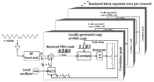
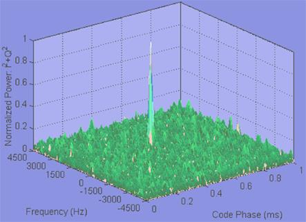
GPS Acquisition:
• Simultaneous
(2D) search Doppler frequency shift and code offset (delay)
• Correlation:
multiplying GPS signal with a locally generated version of the satellites CDMA
code with a given delay.
• Integration:
search of the exact delay producing the maximum correlator output. 1ms(=C/A
code repetition time) for strong signal. For weak signals, the integration time
increased to enhance S/N.
• Time for
Doppler frequency fix: proportionally increased as integration time increased.
• Acquisition
time: proportional to the square of integration time. N2
• World record:
-183dBW using 265ms integration period
• Cross correlation:
correlation between SV codes. less than autocorrelation by 24dB.
• Doppler
processing: sequential method (slower, overall acquisition time N2), non-sequential FFT
method (faster, overall acq. time, N1.5)
Code and
carrier PLL: to track time delay, carrier phase, frequency
Code
Tracking Loop:
Equivalent code loop noise bandwidth. If the code loop operates
independently of the carrier-tracking loop, then the code loop bandwidth needs
to be wide enough to accommodate receiver dynamics.
Predetection integration time = post-correlator IF bandwidth
Wavelength of the PRN code: 29.305 m for P-code, 293.05 m for
C/A-code
DLL discriminator correlator factor
Code tracking loop jitter: positioning random error due to code
tracking loop noise
![]()
Correlator:
Using the dedicated baseband processor
By SW residing in an application processor of a handheld device
(such as the Philip's software GPS technology "Spot"): drastic
reduction of the size of the GPS solution.
Number of
correlators: directly affect TTFF and SNR, a few hundred correlators per
channel are not adequate.
Large number of
correlators: fast fix with low signal level.
NavSync CW25
chip: 12,288 correlators per channel. massively parallel search is possible. signal
sensitivity as low as -155dBm can be tracked - tracking sensitivity (27dB down
from normal level). Correlation gain 20-30dB.
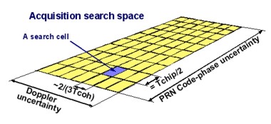
Code search
resolution cell (code phase search): 1/2 PN chip. In the worst case, all the
resolution cells in the entire uncertainty region must be tested before the
signal is detected. Statistically half of the total number of resolutions cells
must be tested. 511 resolution cells in time are tested in parallel. Code phase
search is same as shifting the phase of the replica PRN code generated by the
receiver until it correlates with the received satellite PRN code.
Frequency
search resolution cell (carrier phase search): reciprocal of the coherent
integration period, use FFT to extend 511-time resolution cells to 64-frequency
resolution cells. 511x64 = 32704 time-frequency resolution cells. Carrier phase
search is same as changing the receiver frequency until it correlates with the
received satellite carrier frequency plus Doppler.
The
FFT search method is extremely efficient and effectively accomplishes massive
parallel correlation comparable to the tens of thousands of correlators needed
to acquire weak signals using serial search techniques. Since acquisition does
not need to be a real-time continuous operation, it can be performed using a
snap-shot technique to search for signals only when needed, saving both cost
and circuit real-estate compared to a dedicated massive correlator chip.
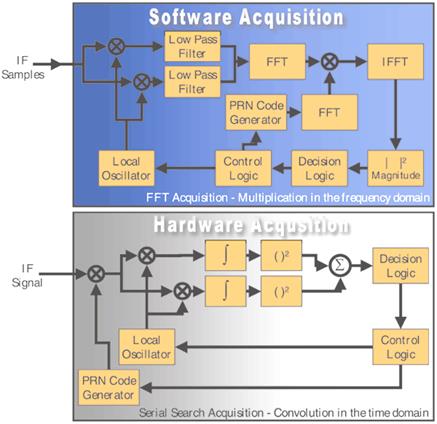
The
hardware search is a sequential serial search in the time domain using correlation
techniques; whereas, the software search involves buffering samples to
facilitate a Fourier transform. This operation is accomplished in the frequency
domain by making use of the fundamental mathematical relationship that
multiplication in the frequency domain is equivalent to convolution in the time
domain (and vice versa). Acquisition techniques in software also complement
assisted GPS (A-GPS) information as an SDR is easily tuned depending on the
quality of the aiding information.
GPS signal acquisition:
1)
Serial search
2)
FFT-based acquisition = parallel code phase search: ���ű�� ������ gps ��ȣ�� FFT�� ���ŵ� GPS ��ȣ�� FFT�� �����Ҽ��� ���� �� �̸� IFFT�� �ð��������� ��ȯ.
3)
Correlator-based acquisition = parallel frequency space search: ���ű�� ������ gps C/A �ڵ�� ���ŵ� GPS ��ȣ�� convolution�� �ð���� ����(time shift of 50us and multiplication)
4) Carrier freqeuncy acquisition:
������ȣ�� GPS���� ������ RF ��ȣ�� ���ļ��� ������ C/A �ڵ��� 1�� ��(�� 1024�� ���� Gold code �� ���� �ϳ�) �ֱ� �� 1ms ���� �ξ� �۾ƾ� �Ѵ�(��10ms)
���ļ� search: ��10kHz Doppler
search, 100Hz frequency bin spacing
-
Frequency search bin width: 1000/(correlation shifting time/code chip period)
Depends on
the desired integration time and the desired maximum SNR loss due to frequency
mismatch.
Commonly
used bin size = 500Hz
-
Frequency search width:
Doppler
shift due to satellite velocity: ��5kHz
GPS
receiver oscillator's frequency offset: 1.575kHz/1ppm. Typical oscillator = ��1
to ��3ppm. A value of ��5kHz is a safe choice.
GPS
receiver velocity: ��5.25kHz at 1000m/s
-
Number of frequency search bins = Search width/bin width = 20kHz/100Hz = 200
5)
Time (code) space search
- Time
step: depends on desired correlation (SNR) loss due to misaligned spreading
code phases. Typical value is 1/2 of a chip.
[L2 Codeless Reception]
dunn-codeless gps.pdf
spectracom-codeless gps.pdf
leyssens-commercial dual-freq gps receivers.pdf
trimble-sps855-datasheet.pdf
Method: carrier phase or codeless receiver (some
commercial receivers)
Commercial receivers:
iGage:
X90-OPUS, $2450, L1/L2/L2C
Trimble
SPS855 GNSS modular receiver, with antenna option GA810
Septentrio
PolarRx2, 48-channel dual-frequency, L1/P1/P2
[GPS Jamming]
gerden-gps jamming.pdf
astech-z-12 gps receiver.pdf
GPS
filter:
70 dB rejection of the out-of-band signal
Maximum out-of-band jamming level = –47 dBm; Telemetry transmitter
= 27 dBm, Tel-GPS antenna isolation = 60 dB, GPS filter out-of-band rejection =
70 dB �� –103 dBm
Anti-jamming
techniques:
Navigation signals of opportunity: INS, Loran. �ǵ�/���ǵ��� RFI, �dz�/������
Null-steering: GPS ��ֽ�ȣ �������� ���׳� null ����
CRPAs(controlled radiation
pattern antennas):
IM(inertional measurement):
IM�� ����Ͽ� GPS Ž���뿪���� ����. �� ��� RFI�� ������ ���� �� ����.
JPALS(Joint Precision
Approach and Landing System): IM�� beam
steering ����.
Adptive filter method
[GPS �ڰ�����]
�ڰ�����(self jamming)�� ����: GPS ȸ�ο� ������ �����ϴ� �ٸ� ȸ�ηκ����� ��������
�ڰ������� ����:
1) ����Ʈ���м���: �ּҽ�ȣ���� ������ �� �ֵ��� ���� (��ȣ ���ΰ��� ǥ�õǴ� ����Ʈ���� �������� ����Ʈ���м��� ������ ��)
2) GPS ���ű� �Է´����� ���ԵǴ� ������ ����: �� �� ���������� ���� ����ϴ� ���ἱ�� ���� ����η� �����ϸ� �ȵ�.
3) ��������� Ȯ��:
�� ȸ�ο��� ���� ������ ���׳��� ���ŵǾ� GPS ���ű� �Է´����� ����: ���׳��� 1m �̻� ȸ�ηκ��� ����߸��� ����. ���׳� ��� ���պ��ϸ� �����ϰ� ����
�� ȸ�ο��� ���� ������ ȸ�μ��ο� ���ŵǾ� ����: �ٸ� ȸ�� ���� ������ ��� ��ȭ ����.
�� Ÿȸ�ηκ��� ������������ Ÿ�� GPS ���ű�� ����: �ٸ� ȸ�� ���� ������ ��� ��ȭ ����. GPS ���ű �ٸ� ����(����) ����Ͽ� ����.
�� Ÿȸ���� ������������ ���׳� ������ ����Ǿ� ���׳��� ���� ����: �ٸ� ȸ�� ���� ������ ��� ���׳�/���׳� ��� ���պ��� �����Ͽ� ������ ����.
�� �ֺ�ȸ�ΰ� ���� �� ���� ��� ���������� ������ �������� �������� ã�� ��. �ֺ�ȸ�ΰ� Ư���� ������ �� �� (��: ����ũ�����μ��� ���ý�) �� ���� ������ ���ԵǴ��� Ȯ��.
�ڰ����� ����/����:
1) ���� ��� �ֺ�ȸ�ο��� ���� ������ ������ �����ϱ�� ���. GPS ���ۿ� ������ ���� ���� ������ ���ҽ�Ű�� ���� �߿�.
2) �ֺ�ȸ�ο��� ���ϴ� ������ ���ļ� �м�. �������ڿ� ���� ������(harmonics), ȥ�ձ ���� �����ļ� ���� ����.
3) Ŭ�Ͻ�ȣ�� ���� ������ ���� ���� ��: squared clock signals
4) �پ��� �������� ��å:
�� Decoupling capacitor: 15 pF for 0402 packages.
�� 10–100 W resistor: to remove high frequency transients
�� Ŭ���ȣ ���������� metal shield
�� ���ϱ��ǿ� Ÿȸ�� ����� �ڰ������� �����Ͽ� ���� ���̾ƿ� ����
���׳��� ���� �ڰ�����:
���׳��� ���� ������ ������ ���� (CCMN)�� ���������� �ֿ��� ������ �� �� ����. ��������(single-ended) ���׳�(��: �����)�� CCMN�� ���ű��� �Է����� ������Ŵ. ���� ���׳�(��: ��Ī���� ������, quadrifilar helix)�� CCMN�� ���ű�� ������Ű�� ����
�ڰ������� ���� ��� GPS ����:
GPS�� CDMA ����� ����ϱ� ������ �ڰ������� �ִ��� ������ ������ ���ϵ�. ���� GPS ����(�ʱ������ð� ��) ���������δ� �ڰ������� ��Ȯ�ϰ� ���� �� ����.
�ڷ���Ʈ�� �۽ű ���� GPS ���ű� ����:
L-�뿪 TM �۽ű�: 1435.5/1535.5MHz, +34dBm
GPS L1 �뿪 ����: L-�뿪 TM ���׳��� GPS L1 ���׳��� �и����� 30dB �̻� �Ǿ�� GPS ���ű� ���� [Richen et al.]
��������
Sarantel
Inc., "Detecting and prevention of self-jamming signals", Application
Note AN-09 v2 Iss 4-06, 2009.: ���׳��� ���� �ڰ�����
H.
W. Ott, Electromagnetic Compatibility
Engineering, Wiley, 2009.: �������� ���
A. Richen
et al., "Improving interoperability of GPS and L-band telemetry with
shaped-pattern antennas": L-�뿪 �ڷ���Ʈ�� �۽ű ���� GPS ���ű� ���� ���� ���
[AGPS, A-GPS]
tester-fast hot start.pdf
lamance-agps.pdf
diggelen-a-gps.pdf
A-GPS ������:
�����˵�(ephemeris): �������� �����Ͽ� ���� ��Ÿ�(�̵���ȭ, DMB, FM/AM ��� ���ļ�)���� GPS ���ű ����
���� clock ����: �������� �����Ͽ� ���� ��Ÿ�(�̵���ȭ, DMB, FM/AM ��� ���ļ�)���� GPS ���ű ����
GPS time calibration: �̵���ȭ������ �⺻���� ����. ������ ���� �̻����� reference oscillator(���ڽð�) ���ļ��� ��50ppb (= 5��10-8 statiblity)
�̳��� ��Ȯ�� ������ ����. �̵���ȭ�� cell tower
oscillator�� locking�� VCO ���������ν� GPS ���������� ���ļ��� ��100ppb(= 10-7 stability) ����.
GPS frequency locking: �̵���ȭ������ �⺻���� ����
GPS ���ű� ��ġ����: �̵���ȭ���� Wi-Fi cell ID �̿�. ��Ȯ�� 300m �̳�
��Ÿ����� clock timing�� ������ ���� ����:
![]()
1m of clock accuracy = 3ns time accuracy
SV clock with relativistic correction: relative motion
+ gravitational force �� special relativity and general relativity theory �� A
clock on an SV run faster by 38ms per day than one on the Earth surface.
Fine-time acquisition sensitivity:
Coarse-time acquisition sensitivity:
SV atomic clock accuracy: ��1ns
GPS timing signal accuracy
GPS Positioning Error (1 sigma):
(��������)
langley-dop.pdf
http://nptel.iitm.ac.in/courses/Webcourse-contents/IIT-KANPUR/ModernSurveyingTech/objectives/B_11_Objectives.htm
: Module 2: Global Positioning System, Lecture 11: Satellite geometry and
accuracy measures
http://en.wikipedia.org/wiki/Error_analysis_for_the_Global_Positioning_System
���������� �ڷ������ ������ ����. ������ Wikipedia���� �ο��� ��ġ.
Signal arrival: ��3m
Ionosphere: ��5m
Ephemeris: ��2.5m
Satellite clock: ��2m
Troposhere: ��0.5m
Multipath: ��1m (��Ȳ�� ���� �ٸ�)
Receiver noise: ��0.0m (���ű�� ��Ȳ�� ���� �ٸ�),
3sR = ��6.7m
Satellite clock errors: Coeffients of the behavior
of the satellite clocks are included in the broadcast navigation message. The
correction is generally less than 1ms and the broadcast correction has a
typical accuracy of about 5 to 10ns or equivalent 1.5 to 3m. As the satellite
clock error is common to all receivers simultaneously tracking the same
satellite, the effect can be removed by single differencing measurements
between receivers.
Ephemeris errors (orbital errors): Obital errors
are due to errors in the broadcast ephemerides and typically range from 2 to
10m. Can be removed by single differencing measurements between two receivers
with remaining error being 0.5ppm of the distance between two receivers.
Ionosphere-induced errors: a few meters at the zenith
and many tens of meters at the horizon. Single frequency GPS receivers use a
set of broadcast ionospheric correction coefficients included in the GPS
navigation message. Can be significantly reduced by single differencing
measurements between two receivers.
Tropospheric effects: 0.4dB attenuation at horizon,
0.04dB at zenith. 2m at zenith and 25m at horizon. Trophospheric models can
typically correct for about 90% of the delay.
Multipath errors: much more probable and
significant in HSGPS receivers. Most multipath mitigation techonologies are
based on the design of suitable architectures in receivers that can minimize
multipath and there are also special antenna designs such as choke rings and
other multipath-limiting antennas. The standard correlator has a spacing of 1.0
chip between the early and the late correlators and precorrelation bandwidth of
2MHz. In contrast, the Narrow CorrelatorTM
has a precorrelation bandwidth of 8MHz and a correlator spacing of 0.1 chip
between the early and the late correlators.
 (maccougan-hsgps.pdf)
MET(multipath estimation technique)
MEDLL(multipath estimation delay lock loop)
Error components are all independent that the total
error is the root-sum-square(RSS) of individual errors.
![]()
![]() : UERE(user equivalent range error)
: UERE(user equivalent range error)
![]() (error in estimated receiver position)
(error in estimated receiver position)
PDOP: 0-4 = excellent positioning, 5-8 =
acceptable, 9-99 = poor
PDOP calculation:
(x, y,
z): receiver position
(xi, yi, zi):
SV position
![]()
![]()
![]()
![]()
![]()
wieser-positioning error due to noise and
multipath.pdf
Information supplied to the receiver: receiver
location (approximate), UTC (approximate), almanac, ephemeris
UTC time aiding: fine aiding ��10us, coarse aiding =
��2s
With no external aiding: typical GPS time drifts at
a rate of around 0.06ms/min resulting in the loss of the 1ms epoch within 15
min.
Lack of time aiding and knowledge of variation in
reference frequency limits the aided hot-start TTFF. Provision of accurate time
aiding allows the code-phase search space to be minimized.
The exponential increase in frequency-code phase
search space results from the loss of accurate time and the uncertainty around
local receiver reference frequency.
As received GPS signal strength decreases from
-130dBm to -160dBm the resulting coherent integration time required to maintain
target SNR increases with corresponding decrease in bandwidth of each search
bin from 500Hz to 10Hz.
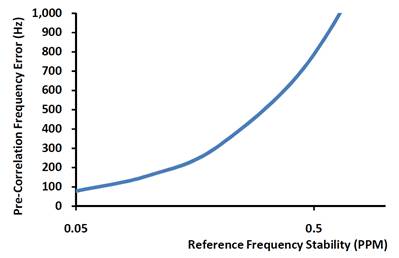
Stability of the local reference frequency
translates to error in conversion of the RF signal to IF due to difference
between the locally generated LO and the target mixing frequency. Mixing RF to
IF results in additional pre-correlation frequency error, which will depend on
reference conditions. 0.5ppm reference stability leads to frequency error of
788Hz.
Cell phone GPS assistance
data: �̵���ȭ ��ȣ�� ���� GPS ������ȣ�� ����. �ش� ������ ���� �ִ� �̵���ȭ�� replacement navigation
message�� �۽�(satellite Doppler shift ������ ���������μ� ���� �� ���нð� ����(�뿪�� ����)�Ͽ� S/N�� ����). �̵���ȭ ���ļ��� �̿��Ͽ� cell phone �������� ���ļ��� locking�Ͽ� Doppler search ������ ����.
Assisted GPS(AGPS):
• IF the time
of day is given with an accuracy of X
microseconds, then the complexity is reduced from C(with no time aid) to ceil(1.023X)/1023*C, where ceil(y) is the smallest integer greater than y. If X = 10 ms, then complexity is reduced by roughly 99%.
• Receiver
always being powered and assistance data always received.
• Relay
information (= assistance data) to GPS receiver to help shorten acquisition
time.
- SV
ephemeris (orbit parameters): mandatory
- SV clock
corrections: mandatory
- Other
error corrections: ionospheric, tropospheric
- Accurate
local time: produces 3dB sensitivity improvement
- GPS
receiver (UE=user equipment) location
- Visible
satellites
- Relative
code delay offsets
- Doppler
frequencies
- DGPS
corrections (optional)
-
Navigation message bits: produces 3dB SNR improvement
• GPS receiver
maximum distance from server station: 150km
• Benefits:
- Search space is
drastically reduced. 100-1000 times faster in all SNR conditions
- SNR (code phase
tracking) improvement: 25dB, operation in low signal and heavy
multipath
environments (foliage,
indoors, urban canyons).
- TTFF
almost independent of SNR.
- Indoor operation of GPS is possible.
- Accuracy: 4m
open sky, 20-50m(indoors, urban canyons)
[Self-assisted GPS]
tester-fast hot start.pdf
When tracking the GPS transmission, the receiver is
locked directly to GPS time and whilst not tracking, the receiver local time
will drift compared to satellite time. The rate of drift depends on the
relative performance of the receiver's ability to either predict reference
variations or maintain the frequency reference with known performance.
Maintaining an accurate local estimate of system
GPS time enables self-assistance. The receiver has no absolute time or
frequency reference and must make time hypothesis which are validated against
the GPS signal itself to ensure local receiver time predictions remain within
suitable tolerances. This requires the receiver to periodically activate and
re-lock to the GPS transmission. Existence of accurate local time enables used
of minimum size search windows for re-detection of the GPS satellite signals.
The fine-time self-assistance approach forms the
basis of a recent GPS receiver development. Unfiltered CEP50 position accuracy
(over 12 hours) for the receiver operating without a Kalman filter is 2.8m and
the self-assisted hot-start TTF is 2.5s over signal power -130dBm to -150dBm.
Alternate approaches require 200,000+ correlators and network aiding
information to deliver comparable TTF.
[HSGPS(High Sensivity GPS)]
hide-hsgps.pdf
[GPS Receiver Startup Modes]
surveylab-gps startup modes.pdf
agilent-gps fundamentals.pdf (�߰��۾� �ʿ�)
Factors affecting TTFF:
SV
almanac: determine which satellite is overhead. Data valid for 3 months.
SV
ephemeris: precise orbital information. Data valid for 4 hours.
Received
signal levels
Receiver
location
Clock
accuracy relative to UTC
Cold start
Warm start: almanac, receiver location within 60
miles, time (less than 3 days passed since the receiver was synchronized with
UTC)
Hot start: position fix within the last 2 hours,
ephemeris data for at least 5 satellites
Factory start:
• Receiver
never used since fabrication
• Receiver not
powered for more than a year.
• No
information at all on GPS satellite. The GPS receiver chip has never been fully
operated after its semiconductor fabrication.
• Almanac
download alone takes 12.5 minutes.
• TTFF = 13.5
min.
Cold start:
• Receiver not
powered for 8-12 hours.
• Almanac in
non-volatile memory is valid.
• Invalid
ephemeris (older than 4 hours): ephemeris data is broadcast every 30 seconds.
• Receiver
position not valid: away from previous fix by more than 100km
• Receiver
time: unknown
• Receiver
works through an internal list of all satellites acquiring each SV in view in
turn. Acquisition time is the longest among all start-up modes.
• TTFF = 30-40s
@ 2011
• Forced cold
start: wrong information (very old almanac) on SV will make receiver spend more
time than in the total cold start mode. In this case, a forced cold start is
necessary.
Warm start:
• Receiver not
powered for 30 minutes.
• Valid almanac
• Invalid
ephemeris (older than 4 hours)
• Receiver
position: approximately known (within 100km of the last fix)
• Receiver
time: approximately known (GPS has been active in the last three days or RTC
has been on by backup power).
• Receiver
immediately detects overhead SVs but needs to download current ephemeris data.
• TTFF = 30-40s
@ 2011 (not much different from cold-stat time)
Hot start:
• Receiver not
powered for 15 minutes.
• Valid almanac
• Valid
ephemeris data for at least 5 SVs (less than 4 hours old)
• Receiver
position: not changed (exactly known)
• Receiver
time: exactly known
• Receiver
rapidly tracks overhead SVs and needs to download a minimum of data.
• TTFF = 1s @
2011
Reacquisition:
• Receiver
always being powered. After blockage for up to 10s while tracking SV signals.
• TTFF < 1s
@ 2011
(����)
- ������ GPS ���� chip ��; hot start = 1s, cold and warm start = 27s
- Cold start�� ����� ����� almanac data ���. ��� 3������ ������� ������ ��ȿ��.
- Warm start�� ������ ȹ���� almanac data ���. �̿� ���� cold start �ð��� warm start �ð����� ���̰� ����.
- Cold start�� warm start�� ��� �ð��� ���ļ� ������ �����Ƿ� ���� �� ����Ʈ���� �������� �ð� 0.5�� ����, time/frequency search�� �� 2.4��, �������� ������ ���ſ� 24�ʰ�, ��ġ��꿡 0.1�� ���� �� �� 27�� �ҿ�.
- Hot start�� ��� ���� �� ��Ʈ���� �������� �ð� 0.5�� ����, time/frequency search�� 0.1�� ����, ��ġ��꿡 0.1�� ���� �� �� 1�� ���� �ð� �ҿ�.
Carrier phase measurements:
For correct tracking of arrival times
The number of carrier wavelengths and fractions of
carrier wavelengths between the receiver and the transmitter.
GPS-based phase
interferometer: differential carrier phase GPS (�װ��о�), RTK(real time kinetic)(�����о�). ���ؼ��ű�κ��� 1000bps �̻��� �ӵ��� GPS �����ȣ�� �Ƽ� �̵����ű��� ����� ��. ���ر��� �̵��� �Ÿ��� 10km�� ��� 1-cm �� ��Ȯ��, 100km�� ��� 10-cm�� ��Ȯ��. RTK�� carrier phase �̿�(at the expense of ambiguity) 0.5cm ���ش�. Code phase measurement�� 1m ���ش�.
Carrier phase ������ 2��N ambiuity�� �ذ��ϱ� ���� �پ��� �˰������� ���ߵǾ���. ������ �˵��� ����� ������ ������ ��ٷ��� N ����. L1�� L2�� ����Ͽ� wide-lane�� �����Ͽ� ������ �ȿ� N�� ������ �� �ִ�. L1/L2/L5 ��ȣ�� �̿��Ͽ� N�� ���� ������ �� �ִ�.
Non-dispersive ����(���̿��� ����): L1/L2/L5 ��ȣ�� �̿��ϸ� �� ������ �̿��������� ���̿�������(�������������)�� ����.
Carrier-tracking
loop:
- Costas-type phase locked loop
- Carrier loop noise bandwidth. Must be wide
enough to follow the receiver dynamics.
- Carrier tracking loop jitter:
![]()
[High-End Professional GPS Receivers]
Novatel
Septentrio