GPS
Munitions
[Introduction]
- GPS guidance:
cheaper and more accurate than INS, vulnerable to jamming.
ECCM-equipped GPS receiver is used.
- DGPS: A
DGPS receiver improves the GPS accuracy. A C/A based
DGPS is accurate within 1-3 m and employed in Cat III Instrument approaches and
landings for aircrafts.
- The central idea behind the
design of DGPS/GPS/inertial guided weapons is that of using a 3-axis
gyro/accelerometer package as an inertial reference for the weapon's autopilot,
and correcting the accumulated drift error in the inertial package by using GPS
PPS/P-code. Such weapons are designated as "accurate" munitions as
they will offer CEPs (Circular Error Probable) of the order of the accuracy of
GPS P-code signals, typically about 40 ft. The next incremental step is then to
update the weapon before launch with a DGPS derived position estimate which
will allow it to correct its GPS error as it flies to the target, such weapons
are designated "precise" and will offer accuracies similar to laser
or TV guided weapons, potentially CEPs of several feet.
- The SRI developed wide area DGPS
network used for the USAF EDGE project trials (Part 3) demonstrated accuracies
within 0.5 meters. The accuracy of DGPS allows both blind bombing and munition
guidance with accuracies very similar to that achieved by using laser or TV guided
bombs.
- What is even more important, is
that GPS guided weapons can be fed DGPS derived positions prior to release from
an aircraft, and should their flight time be relatively short, very little
positional error will be accumulated en route to the target. Many existing
munitions, e.g., the BGM-109 Block III Tomahawk and the AGM-130/GBU-15 already
exploit P-code GPS to improve the accuracy of the inertial midcourse guidance.
Adding DGPS corrections will significantly improve the positioning accuracy of
the weapon prior to transitioning to terminal guidance. To extend this model
further, an aircraft could transmit via data link both DGPS corrections as well
as the updated position of a moving target to a weapon in flight, which would
use these to adjust its aim point on the way to the target.
[Mk.84 GAM]
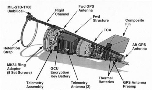
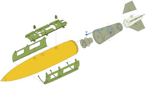
The Mk.84 GAM
comprises a 100 lb tail kit which fits into to the
standard Mk.84 slick form factor. The tail cone contains a pair of thermal
batteries which power the munition, a servo-motor assembly which actuates the
four fully movable tailfins, and a guidance system, which comprises a high
performance GPS receiver, an inertial package with accelerometers and rate
gyros (the same as used in the AIM-120 AMRAAM), and a computer running the
guidance algorithm and autopilot software.
Two GPS antennas
are used, one dorsal and one at the end of the tail cone, the latter to provide
good GPS signal during the terminal phase when the bomb is pointing downward.
The GAM has
proven to be highly accurate during trials, with better than 20 ft CEPs
achieved consistently for launches from 15,000 to 45,000 ft. The reason for
this high level of accuracy is the B-2's GPS Aided Targeting System (GATS). The
GATS is built around the B-2's Hughes AN/APQ-181 J band phased array Low
Probability of Intercept attack radar (a worthy TE topic within itself), which
is capable of producing highly accurate focused Synthetic Aperture Radar (SAR)
imagery of a target area as the bomber approaches.
The B-2 will
attack its target flying a curved trajectory to enable the SAR to generate
images. Nine minutes out and with the target cca 45
degrees off boresight, the B-2 will image the target and the copilot/mission
commander/navigator/bombardier (all in one) will use crosshairs on his cockpit
scope to designate aim points for the weapons on the radar map. Ninety seconds
off the target, the radar again generates an image and the aim point(s) are if
necessary refined. The GAMs assigned to the target are then initialized via the
1760 interface with the target coordinates and the constellation of satellites
which the bomber's GPS receiver is tracking. The bombs are
then released and track to impact.
High accuracy is achieved because the bombs see the same satellite
constellation the bomber sees, and thus experience almost identical GPS errors
to the bomber. The bombs are initialized with an aim
point relative to the bomber, rather than an absolute set of map coordinates,
and the primary errors are then determined by the inaccuracy of the bomb's
guidance algorithms and the range/bearing calibration error of the radar. This
scheme is very clever and a tribute to Northrop and Hughes' engineers.
[JDAM]
The baseline
JDAM program provides a design for the GBU-31/Mk.84 and BLU-109 2,000 lb
weapons and the GBU-32/Mk.83 and BLU-110 1,000 lb weapons for use on the USAF
F-15E, F-16C, F-117A, F-22, B-1B, B-2A and B-52H, the USN F-18C/D F-14A/B/D and
the USMC AV-8B and F-18C/D. The baseline accuracy for the weapon is a CEP of 42
ft (13 m) with a target volume production cost between USD 14k and 25k/round,
which is highly competitive with laser guided weapons.
Martin-Marietta (prior to merger with Lockheed) and MDC competed for the
lucrative contract, with MDC winning the eventual prize.
JDAM-PIP(Product Improvement Program)
US industry
sources suggest that JDAM accuracy improvement may involve the use of a millimetric wave radar seeker, which would employ SAR
techniques and terrain contour matching to achieve precision delivery accuracy.
Whether this is required, given the availability of Scene Matching Area
Correlation algorithms and existing millimetric wave
seekers such as that used on the BAe Merlin mortar round, is clearly open to
debate. In any event, a number of techniques exist for using miniature radar
seekers to refine the bomb's aim point.
When the weapon
is released, the thermal battery is fired, the JDAM
acquires a self-determined, optimum satellite constellation, and flies itself
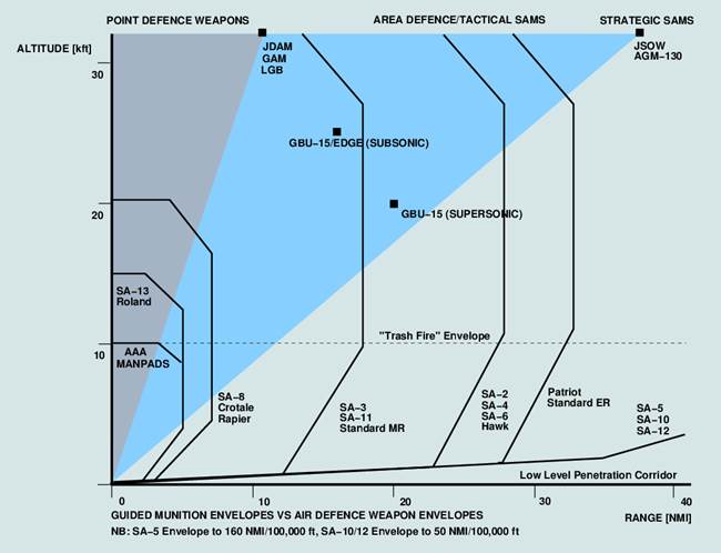
autonomously to impact. The JDAM delivery envelope is identical to that of the
dumb Mk.84, Mk.83 and BLU-109 bombs. The weapon can be delivered from up to 50 kft, at speeds of up to 1.3 Mach, using direct (boresight)
and off axis trajectories. Accuracy has not been disclosed
but will depend critically upon the launch aircraft's capability.
While the JDAM is expected to become the principal all weather
"bread and butter" munition for US services, it is not expected to
wholly replace all seeker equipped weapons. This is
because seeker equipped weapons, using millimetric
wave, optical and Synthetic Aperture Radar techniques are
becoming more cost competitive, and can operate even in environments
where a sophisticated GPS jamming threat or poor GPS reception exist. Moreover,
autonomous seeker equipped weapons can achieve high accuracies often with
limited support from a launch aircraft. We can therefore expect that the US
munitions inventory early in the next century will comprise mainly JDAMs, supplemented by seeker equipped
weapons, to provide the diversity to deal with a wide range of delivery platforms,
conditions and jamming threat environments.
While the JDAM is expected to become the principal all weather
"bread and butter" munition for US services, it is not expected to
wholly replace all seeker equipped weapons. This is
because seeker equipped weapons, using millimetric
wave, optical and Synthetic Aperture Radar techniques are
becoming more cost competitive, and can operate even in environments
where a sophisticated GPS jamming threat or poor GPS reception exist. Moreover,
autonomous seeker equipped weapons can achieve high accuracies often with
limited support from a launch aircraft. We can therefore expect that the US
munitions inventory early in the next century will comprise mainly JDAMs, supplemented by seeker equipped
weapons, to provide the diversity to deal with a wide range of delivery
platforms, conditions and jamming threat environments.
There are three
basic sources of error when delivering any munition,
these are the target location error (TLE), navigation
errors and guidance errors. In a GPS based system, the navigation error is
produced primarily by three mechanisms, which are uncompensated atmospheric
transmission delays in the satellite signals, errors in the satellite's onboard
atomic clock and orbital ephemeris data transmissions, and GPS receiver errors
caused by noise and multipath.
The conventional
commercial DGPS schemes in use provide a "band-aid" fix to compensate for dither and atmospheric
delays, and satellite orbital and clock errors by measuring pseudo-ranges to satellites
from a precisely surveyed location, and using these to calculate a correction which is broadcast to aircraft by a radio beacon.
To defeat (Selective Availability) clock dithering, the updates must be as
frequent as one per second, to preserve satellite visibility relationships
between the ground station and GPS user, the coverage is typically limited to
about 300 NMI. A number of commercial DGPS schemes exist which use dedicated radio datalinks, and
one which piggybacks the DGPS
signal on to commercial FM radio transmissions. The latter is accurate to 1 metre at 75 NMI.
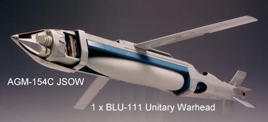
[JSOW]
- Joint Stand
Off Weapon, AGM-154, Texas Instruments
The primary role
of the weapon is to enable indirect attack against vehicular, air defence and other soft or semi-hard targets from outside
the range of point air defences, with a lethality similar to that provided by cluster weapons such
as the Rockeye and APAM,
and with high accuracy.
The nucleus of
the JSOW navigation/guidance is a mission computer package with a pair of Milspec Intel 486 33 MHz CPUs, a Singer Kearfott
inertial package and a GPS receiver. Power to the guidance
systems and Lucas Aerospace control actuators is provided by Eagle Pitcher
thermal batteries.
The JSOW design
will provide a standoff range of 15 NMI for a low level
release, and 40 NMI for a high altitude release. The weapon can turn through
180 degrees to engage off boresight targets. Moreover, the smarts provided by
two fast CPUs allow the weapon to perform some very clever tricks. On release the weapon will separate laterally from the launch
aircraft, before it deploys its wings and commences its glide, to ensure safe
clearance. Once programmed, as long as it is released
at such an altitude and range to be able to aerodynamically reach its target,
it will autonomously calculate the flightpath and profile to correctly engage
its target.
If
released at high speeds, it will delay wing deployment to avoid penalising its range by drag, the wing is deployed when
most appropriate. The weapon can also be programmed to attack a target from a specific
heading, and to fly between multiple programmed waypoints. A typical profile
will see the weapon glide in at several hundred feet, pop up close to the
target and dive in to dispense its payload from several hundred feet.
[USAF EDGE High Gear Program]
The purpose of
the EDGE (Exploitation of DGPS for Guidance Enhancement) High Gear program was
to demonstrate the military potential of wide area differential GPS techniques
for weapon guidance, by achieving accuracies better than 3 metres.
The program was a stunning success, yielding what should be
regarded as remarkable results.
The EDGE program demonstrated that appropriate use of DGPS techniques can provide military aircraft and munitions with sub-metre positioning accuracies in all three axes, over areas
of continental sizes.
Military DGPS schemes can be somewhat more robust, jam resistance is
inherently better with P-code systems, dither is not an issue and the receivers
can further compensate ionospheric delays by comparing the L1 and L2 GPS
carrier signals. Tropospheric delays can be reduced by
using error models embedded in the GPS receiver firmware. At a minimum a
military DGPS scheme need only compensate for satellite clock offset error and
orbital position drift. As a result, a military DGPS scheme can cover wide
areas and use fairly sedate update rates as slow as 1
update per 30-45 minutes.
The optimal solution for military WADGPS is to add the corrections to the
existing GPS navigation message broadcast, however due to limitations of the
existing satellites and their supporting ground network this is not a practical
short term proposition. The USAF's follow-on and
separate WAGE (Wide Area GPS Enhancement) program has demonstrated the
insertion of encrypted DGPS corrections into Page 4 of the GPS broadcast
almanac message, and has been used for trials of the
Block II CALCM and a modified AGM-130. It is intended
that the WAGE system eventually transition to an operational system, as the
existing GPS satellites are replaced.
In the near term, any operationally deployed military WADGPS schemes will have
to employ radio datalinks for this purpose, as were used in the EDGE program.
In the longer term, late model GPS IIR "replenishment" satellites,
which employ satellite-to-satellite radio crosslinks, as well as a higher
baseline accuracy of 6 metres rather than 20 metres, and a higher power output for weather penetration
and jam resistance, would be used. These will have the capability to robustly support a fully embedded WADGPS scheme such as
WAGE. The twenty one GPS IIR
sats will be progressively deployed between 1996 and
2006.
The datalink scheme used in the EDGE program comprised the USN developed
Improved Data Modem (IDM), fitted to the F-16D test aircraft and the central
ground station. An encrypted 64 byte correction message included satellite IDs,
pseudorange corrections for 12 satellites, standard
deviations for corrections and the orbital parameters (specifically data used
to select the exact ephemeris pages from the respective GPS almanacs) used in
generating the correction. This message was broadcast from the ground station
to the test aircraft, decrypted on receipt, and used to improve the accuracy of
the aircraft's GPS aided inertial navigation system. Orbital parameters
(specifically ephemeris parameters from applicable GPS almanacs) and corrected
aircraft position were then downloaded via the
Mil-Std-1553B bus to the test munitions.
The EDGE RRN evolved from the long baseline WADGPS experiment, and included
further design enhancements by SRI to enhance its accuracy. The network
employed four ground stations, each no less than 1000 NM from the intended test
range at Eglin in Florida. The stations were placed at
Kirtland AFB in New Mexico, Ellsworth AFB in South Dakota, Hanscom
AFB in Massachusetts and Roosevelt Roads NS in Puerto-Rico, at precisely
surveyed locations. Each ground station comprised no more than a high quality
military 12-channel GPS receiver and choke ring antenna, designed for very low
multipath reception, a desktop computer and a modem. Software running on the
computer would gather GPS measurements, calculate errors for the site, and via
a modem communicate these to a central site. A computer at the central site
would then calculate the proper correction values to be
broadcast via radio modem for aircraft operating in the test area.
While the
hardware requirements for the EDGE RRN were clearly trivial, the SRI developed software which calculated the corrections was certainly not.
A number of rather clever techniques were used,
requiring no less than 40,000 lines of code, to minimise
the resulting DGPS error.
The first technique used was to compensate for carrier phase slips, which occur
when a receiver loses a carrier cycle. This was achieved
by integrating carrier phase. Ionospheric delay was compensated by comparing L1
and L2 P-code measurements with the integrated carrier phase,
in turn multipath and noise errors were compensated by carrier smoothing.
Carrier smoothing involves the continuous integration of the carrier phase with
previous measurements. Thermal drift in the GPS receivers was compensated by
placing them in temperature controlled enclosures.
Once these errors were compensated, tropospheric
delays were measured by long baseline techniques. Tropospheric delays fall into
two categories, a "dry" delay due to pathlength
(slant range to satellite) and a variable "wet" delay, which is a
function of humidity, temperature and cloud cover. To calibrate the
tropospheric model, the ground stations were equipped to measure ambient
temperature and pressure. The atmospheric tropospheric delay was
calculated using differences in satellite elevation angles from the
physically separated reference receivers to yield tropospheric pathlength values.
The final major error source to be compensated was the
solid earth tide error. This error results from the earth bulging due to
gravitational tidal forces, and can be as large as 30 cm in altitude twice
daily, across a 2000 NM distance.
These corrections were combined using a weighted mathematical model which repeated the calculation until an optimal set of
correction values was produced for the region of coverage. The correction
values were then merged to produce a single set of
numbers for transmission to an aircraft, optimised
for the lowest possible error at the centre of the theatre of operations, in
this instance Eglin.
The result of these corrections was a position error which
during the EDGE trials varied between 5 cm and 1.57 m, with an RMS value of 40
cm (15.7 in). On average, the position error was under
18 inches, in a network with reference stations of the order of 2000 NM apart,
with WADGPS updates produced every 6 seconds and each deemed valid for 30-45
minutes. It is worth noting that accuracy in WADGPS schemes improves with
geographical coverage, as more widely spaced reference stations can keep
satellites in view longer and therefore determine their orbits more accurately.
A continental network would do better than the existing EDGE, and a global
network even better.
[EDGE GBU-15 Munition]
While the
hardware requirements for the EDGE RRN were clearly trivial, the SRI developed software which calculated the corrections was certainly not.
A number of rather clever techniques were used,
requiring no less than 40,000 lines of code, to minimise
the resulting DGPS error.
The first technique used was to compensate for carrier phase slips, which occur
when a receiver loses a carrier cycle. This was achieved
by integrating carrier phase. Ionospheric delay was compensated by comparing L1
and L2 P-code measurements with the integrated carrier phase,
in turn multipath and noise errors were compensated by carrier smoothing.
Carrier smoothing
involves the continuous integration of the carrier phase with previous
measurements. Thermal drift in the GPS receivers was compensated by placing
them in temperature controlled enclosures. Once these
errors were compensated, tropospheric delays were
measured by long baseline techniques. Tropospheric delays fall into two
categories, a "dry" delay due to path length (slant range to
satellite) and a variable "wet" delay, which is a function of
humidity, temperature and cloud cover. To calibrate the tropospheric model, the
ground stations were equipped to measure ambient temperature and pressure. The
atmospheric tropospheric delay was calculated using
differences in satellite elevation angles from the physically separated
reference receivers to yield tropospheric pathlength
values.
The final major error source to be compensated was the
solid earth tide error. This error results from the earth bulging due to
gravitational tidal forces, and can be as large as 30 cm in altitude twice
daily, across a 2000 NM distance.
These corrections were combined using a weighted mathematical model which repeated the calculation until an optimal set of
correction values was produced for the region of coverage. The correction
values were then merged to produce a single set of
numbers for transmission to an aircraft, optimised
for the lowest possible error at the centre of the theatre of operations, in
this instance Eglin.
The result of these corrections was a position error which
during the EDGE trials varied between 5 cm and 1.57 m, with an RMS value of 40
cm (15.7 in). On average, the position error was under
18 inches, in a network with reference stations of the order of 2000 NM apart,
with WADGPS updates produced every 6 seconds and each deemed valid for 30-45
minutes. It is worth noting that accuracy in WADGPS schemes improves with
geographical coverage, as more widely spaced reference stations can keep
satellites in view longer and therefore determine their orbits more accurately.
A continental network would do better than the existing EDGE, and a global
network even better.

[AGM-86C CALCM]
- Cruise
missile: improved accuracy with wide-area GPS enhancement DGPS

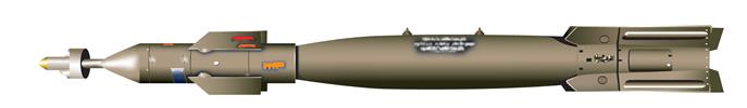
[EGBU-15]
- Glidebomb
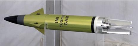
[IMI 105mm Guided
Artillery Munition (GAM)]
- 105mm, 23-km, 10-m CEP
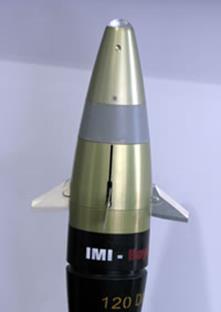
- 120-mm
GPS-guided 120mm bomb: course correction, laser targeting, terminal
control, 10-km range, 1-3m CEP
[GBU-12 Paveway II]
S=1976, L=3.3m, D=0.273m, R=14.8km, CEP=1-2m, Laser/GPS,
[Military
GPS Receivers]
Rockwell MAGR
5-channel GPS receiver: beam steering