CIRCULAR WAVEGUIDE
[Feastures
-
Narrower operating frequency range of the dominant TE11 mode than
the rectangular waveguide TE10 mode
- Offers
lower attenuation other waveguides such as rectangular, elliptical and
truncated types
- Capable
of providing dual polarized operation
- When
the line is not perfectly circular and straight, TM01,
cross-polarized TE11 modes are excited resulting in an increased
loss. To prevent this undesired mode conversion, polarizing pins are used [Fanton], as shown the following figure. These pins have
little effects on the propagation of the TE11 mode.
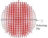
Figure: Higher-order mode suppressing metal pins in
a circular waveguide.
- Lower
wind load when installed along a tower.
- Can
withstand a higher level of pressurization.
-
Circular waveguides often operates above cutoff frequencies of a few
higher-order modes.
[Applications
-
Broadcasting: high-power UHF broadcasting
-
Telephony: AT&T's long distance telephone traffic with more than 15,000
installations in US. The low loss property of TE01 mode is utilized.
- Plasma
heating
-
Reflector antenna feeds
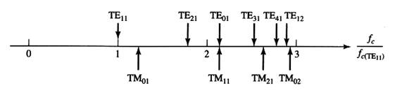
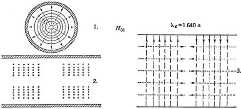
[Cutoff Frequencies and Mode Plots
H mode =
TE mode
|
Modes |
|
|
|
|
TE11 |
1.71 |
3.41259 |
1.00000 |
|
TM01 |
1.31 |
2.61274 |
1.30613 |
|
TE21 |
1.03 |
2.05720 |
1.65885 |
|
TE01 |
0.820 |
1.63979 |
2.08111 |
|
TM11 |
0.820 |
1.63979 |
2.08111 |
|
TE31 |
0.748 |
1.49557 |
2.28180 |
|
TM21 |
0.612 |
1.22345 |
2.78932 |
|
TE41 |
0.591 |
1.18159 |
2.88813 |
|
TE12 |
0.589 |
1.17852 |
2.89566 |
|
TM02 |
0.569 |
1.13824 |
2.99813 |
|
TE02 |
0.449 |
0.897986 |
3.80027 |
- TE11
- TM01
- TE21
- TE01
- TM11
- TM21
[US7208710]
[Mode Properties
TE11 mode: It is the
dominant mode that is employed for the signal transmission using the circular
waveguide.
TE01 mode:
Compared to TE11 mode, it has lower loss, greater power capacity,
larger guide size, simpler flange couplings, and rotational symmetry. Radiation
pattern from TE01 mode guide aperture has a null at boresight and
has only φ component. When the guide
structure is rotationally symmetric, only it couples only to TE0n modes. TE01 can be employed
in implementing a circular waveguide rotary joint and there is no need for
chokes at a break in the guide. At bends, TE01 mode can be converted
its degenerate mode TM11. This can be prevented by introducing
corrugations on the guide inner wall.
Higher-order modes:
- Modes such as TM01,
TE01, TE21 are employed, for
example, in realizing the tracking feed.
- TM11 mode is
employed in realizing a dual-mode feed horn which has a circular symmetric
radiation pattern with linear polarization.
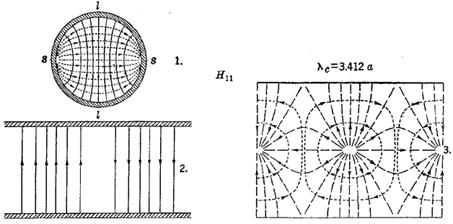
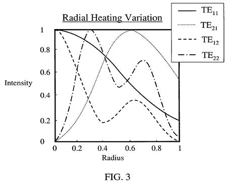
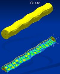
Dominant TE11 mode:
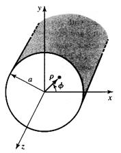
Figure: Coordinae
system for the circular waveguide analysis [Pozar].
![]() (3a)
(3a)
![]() (3b)
(3b)
![]() (3c)
(3c)
![]() (3d)
(3d)
![]() (3e)
(3e)
![]() (3f)
(3f)
[Operating Bandwidth
- Given a mode to be used, the low frequency limit is
determined by cutoff of that band. The attenuation is sharply increased as the
operating frequency approaches the cutoff so that the waveguide is normally
operated from 1.05-1.10 times the cut-off frequency of the mode of interest.
- The dominant TE11 mode cutoff formula:
![]()
- The high frequency limit is determined by the
consideration of exciting higher-order modes in the device chain. When
higher-order modes are well suppressed as in the circular horn, one can use a
large diameter guide. Given a higher-order mode to be suppressed, the high
frequency limit is 0.95 times the cutoff frequency of that mode.
- At waveguide and horn apertures with rotational
symmetry, there are very small mode conversions even when the aperture size is
large.
- The frequency range for which only the dominant TE11 mode propagates is rather
narrow.
![]()
- The recommended frequency range of the commercial
circular waveguide is given by the following equation. This assumes that TM01
mode is not generated or suppressed if generated.
![]()
- In
some design, the upper frequency limit is determined by the cut-off of TM11(and the degenerate TE01) [Lehmensiek]
![]()
Lehmensiek's
example:
Guide
diameter: 184mm → fc,TE11 =
0.955GHz, fc,TM11
= 1.987GHz
Operating
frequency: 1.20-1.95GHz → 1.26 fc,TE11 < f < 0.98 fc,TM11
[Attenuation
- Circular waveguide has
significantly smaller loss than rectangular waveguide. Compare attenuation
curves of both waveguides.
- TE01 mode offers the lowest attenuation. It is often used in
the overmoded waveguide.
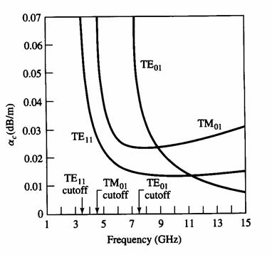
Figure: Attenuation in the
circular waveguide of 2-in diameter (TE11 cutoff at 3.46GHz) [Pozar]
Figure: Attenuation in
rectangular guide with a = 2cm (TE10
mode cutoff at 7.5GHz) [Pozar].
Figure: Attenuation in a
circular waveguide with 2a = 3.0 cm.
[Balanis(1989)]
Figure: Attenuation in a
circular waveguide with 2a = 6.0 cm.
[Balanis(1989)]
[Low-Loss TE01 Mode Circular Waveguide
- Used for long-distance
communication
- Large bandwidth and extremely
low-loss. With a 50.8-mm diameter, the attenuation is 0.7 dB per 100 m at 15
GHz.
- Discontinuites
appear as both resistive and reactive to the TE01 mode.
- A curvature discontinuity: TE01
mode couples to the TM11 mode and to TE1m modes. In a
perfectly conducting straight waveguide, the phase velocity is the same for the
TE01 and TM11 modes that their coupling is a serious
problem.
- Forward and couplings between
the TE01 mode and other modes.
- References
H. E. M. Barlow, et al.,
"Propagation characteristics of low-loss tubular waveguides", 1957.
D. A. Lanciani,
"H01 mode circular waveguide
components", 1953.
[모드변환
1) 동축선–원형도파관
Circular Waveguide Mode
Converters:
- Rectangular TE10 mode to the circular TE11 mode converter is frequently
used. Conversion efficiency is about 99.5%
- Circular TE11 mode is often converted into the
circular TE01 mode
(which has the lowest loss) using the serpentine converter. The efficiency of
the converter is greater than 98%.
![]() [After S. V. Kuzikov,
Inst. of Appl. Phys., Russia]
[After S. V. Kuzikov,
Inst. of Appl. Phys., Russia]
[Open-Ended Circular Waveguide
Radiator
1. Near-field vs angle
R. Cicchetti, "Radiation
from open-ended circular waveguides: a formulation based on the incomplete
Hankel functions," 2008.
Excitation: y-polarized
TE11 mode, a = 0.5λ0, pattern at φ = 0º(H-plane), pattern normalized by the
maximum for r = 0.7λ0

2. Near field vs axial distance
from the aperture [Cicchetti & Faraone]
TE11 mode, a = 2 λ0,
aperture at z = 0, ![]() on the E-plane.
on the E-plane.
REFERENCES
Balanis (1989),
C. A., Advanced Engineering
Electromagnetics.
Fanton, M. D.,
"Waveguide for TV broadcast," Electonics
Research Inc.
Galuscak, R. and P. Hazdra,
"Prime-focus circular waveguide feed with septum polarization
transformer,"
www.attplus.cz/hamradio/projekty/article/Prime_focus_circular_waveguide_feed.pdf
Pozar, D. M., Microwave
Engineering, Second Edition, New York: John Wiley
& Sons, 1998.
Marcuvitz, N., Waveguide
Handbook, New York: McGraw-Hill, 1951.
Cicchetti, R. and Faraone, A., "Radiation from open-ended circular waveguides: a formulation based on the incomplete Hankel functions," PIER, 78, 285-300, 2008.
Lehmensiek, R., I. P. Theron and S. J.
Marais, "Design of the feed horn for the KAT-7 radio telescope,"
Proc. 2009 USNC/URSI Annual Meeting.
www.astro.caltech.edu/USNC-URSI-J/Boulder%202009%20presentations/Monday%20PM%20J2a/J2a-2%20Theron_Kat7_Horn.pdf
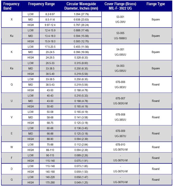
[Appendix - Circular Waveguide Size]
IEC 153-4, BS 9220, N 004
1. EIA Standard
|
EIA Designation |
Innner Diameter (mm)(inch) |
Wall |
Recommended Frequency
Range (GHz) |
TE11
mode Cutoff Frequency(GHz) |
Cover Flange MIL-F-3922 UG |
Flange Type |
|
WC-992 |
251.84 |
|
0.80
- 1.10 |
0.698 |
|
|
|
WC-847 |
215.14 |
|
0.94
- 1.29 |
0.817 |
|
|
|
WC-724 |
183.77 |
|
1.10
- 1.51 |
0.957 |
|
|
|
WC-618 |
157.00
(6.181) |
|
1.29
- 1.76 |
1.120 |
|
|
|
WC-528 |
134.11
(5.280) |
|
1.51
- 2.07 |
1.311 |
|
|
|
WC-451 |
114.58
(4.511) |
|
1.76
- 2.42 |
1.534 |
|
|
|
WC-385 |
97.87
(3.853) |
|
2.07
- 2.83 |
1.796 |
|
|
|
WC-329 |
83.62
(3.292) |
3.30
(IEC), 5.08 (EIA) |
2.42
- 3.31 |
2.102 |
|
|
|
WC-281 |
71.42
(2.812) |
3.30
(IEC), 3.81 (EIA) |
2.83
- 3.88 |
2.461 |
|
|
|
WC-240 |
61.04
(2.403) |
3.30
(IEC), 3.81 (EIA) |
3.31
- 4.54 |
2.880 |
|
|
|
WC-205 |
51.99
(2.047) |
2.54
(IEC), 3.30 (EIA) |
3.89
- 5.33 |
3.381 |
|
|
|
WC-175 |
44.45
(1.750) |
2.54
(IEC), 3.30 (EIA) |
4.54
- 6.23 |
3.955 |
|
|
|
WC-150 |
38.10
(1.500) |
2.03
(IEC), 2.54 (EIA) |
5.30
- 7.27 |
4.614 |
|
|
|
WC-128 |
32.54
(1.281) |
2.03
(IEC, EIA) |
6.21
- 8.51 |
5.402 |
|
|
|
WC-109 |
27.79
(1.094) |
1.65
(IEC, EIA) |
7.27
- 9.97 |
6.326 |
UG-39/U |
Square |
|
WC-94 |
23.83
(0.938) |
1.65
(IEC, EIA) |
8.49
- 11.6 |
7.377 |
UG-39/U |
Square |
|
WC-80 |
20.24
(0.797) |
1.27
(IEC, EIA) |
9.97
- 13.7 |
8.685 |
UG-39/U |
Square |
|
WC-69 |
17.48
(0.688) |
1.27
(IEC, EIA) |
11.6
- 15.9 |
10.057 |
UG-1666/U |
Square |
|
WC-59 |
15.09
(0.594) |
1.015
(IEC, EIA) |
13.4
- 18.4 |
11.649 |
UG-1666/U |
Square |
|
WC-50 |
12.70
(0.500) |
1.015
(IEC, EIA) |
15.9
- 21.8 |
13.842 |
UG-1666/U |
Square |
|
WC-44 |
11.13
(0.438) |
1.015
(IEC, EIA) |
18.2
- 24.9 |
15.794 |
UG-595/U |
Square |
|
WC-38 |
9.53
(0.375) |
0.760
(IEC, EIA) |
21.2
- 29.1 |
18.446 |
UG-595/U |
Square |
|
WC-33 |
8.33
(0.328) |
0.760
(IEC, EIA) |
24.3
- 33.2 |
21.103 |
UG-595/U |
Square |
|
WC-28 |
7.14
(0.281) |
0.760
(IEC, EIA) |
28.3
- 38.8 |
24.620 |
UG-595/U |
Square |
|
WC-25 |
6.35
(0.250) |
0.510
(IEC, EIA) |
31.8
- 43.6 |
27.683 |
UG-383/U |
Round |
|
WC-22 |
5.56
(0.219) |
0.510
(IEC, EIA) |
36.4
- 49.8 |
31.617 |
UG-383/U |
Round |
|
WC-19 |
4.78
(0.188) |
0.510
(IEC, EIA) |
42.4
- 58.1 |
36.776 |
UG-383/U |
Round |
|
WC-17 |
4.37
(0.172) |
0.510
(IEC, EIA) |
46.3
- 63.5 |
40.227 |
UG-385/U |
Round |
|
WC-14 |
3.58
(0.141) |
0.510
(IEC, EIA) |
56.6
- 77.5 |
49.103 |
UG-387/U |
Round |
|
WC-13 |
3.18
(0.125) |
0.380
(IEC, EIA) |
63.5
- 87.2 |
55.280 |
UG-387/U |
Round |
|
WC-11 |
2.77
(0.109) |
0.380 (IEC, EIA) |
72.7
- 99.7 |
63.462 |
UG-387/U-M |
Round |
|
WC-9 |
2.39
(0.094) |
0.380
(IEC, EIA) |
84.8
- 116.0 |
73.552 |
UG-387/U-M |
Round |
|
|
2.08
(0.082) |
|
|
|
UG-387/U-M |
Round |
|
|
1.91
(0.075) |
|
|
|
UG-387/U-M |
Round |
|
|
1.70
(0.067) |
|
|
|
UG-387/U-M |
Round |
|
|
1.50
(0.059) |
|
|
|
UG-387/U-M |
Round |
|
|
1.17
(0.046) |
|
|
|
UG-387/U-M |
Round |
|
|
0.991
(0.039) |
|
|
|
UG-387/U-M |
Round |
3.
Cernex Inc.
[Circular
Waveguide Flange]
Quinstar Corp.: