Rectangular Waveguide Flange
1. Flange Types
1)
Meanings of designation letters
a) EIA
(Electronic Industries Alliance) standards: in North America
Flange designations:
xxR( )
CMR(
), CPR( )
C: connector
M: miniature contact
P: pressurizable contact
R: rectangular waveguide
F: flat
G: grooved
Example: CPR284G, CMR90
b)
BS(British Standards) RCSC
4985-99-( )
c)
IEC(International Electrotechnical Commission)
Flange designations:
IEC 143 IEC-( )
Plain: PAR( ), PBR( ), PCR( ), PDR( ), PFR( ), UAR( ), UBR( ), UER( )
Choke: CAR( ), CBR( ),
P: pressurizable
C: pressurizable choke
U: unpressurizable
R: rectangular
waveguide
A, B, C, D, E, F:
various mechanical features
A: circular
B: square
d)
American Armed Services Standards
Flange designations:
UG-( )/U
418A, 437A, 135, ....
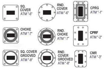
2) Flange Type Identification
- Cover flanges, ungrooved: waveguide walls are in a direct contact.
Holes are all of clearance type. When two cover flanges are mated for outdoor
uses, a special conductive gasket is required.
- Mating

- Square cover flange = UBR

- Circular (= round) cover flange = UAR

- Cover flanges, grooved (with gasket): gasket is installed in flange
mating surface to prevent RF and/or gas leakage or to ensure pressurization.
All holes are of clearance type. Can be mated with choke, cover, and cover
gasket flanges. One gasket is used for cover flange-to-cover gasket flange
mating. Two gaskets are required for mating two cover gasket flanges or for
mating a cover gasket flange with a choke flange.
- Expanded metal gasket:

- Square grooved flange = PBR

- Circular grooved flange = PAR

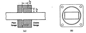
- Choke flanges
(non-contacting): waveguide walls are not in a direct contact.
- Square choke flange = CBR
- Circular
choke flange = CAR
(Square choke = CBR) (Circular choke = CAR)
- Choke-groove flange: contains a
gasket groove, choke groove and tapped holes. Mates with an appropriate cover
flange, but not with choke flange. A single O-ring is used when a choke and
cover flanges are mated. When a choke flange is mated with a cover gasket
flange, an O-ring gasket and a half gasket are required.

 (Square choke grooved = CBR)
  (Circular choke grooved = CAR)
- Contact grooved
- CPRF(Contact,
pressurizable, rectangular, flat) (approximately equivalent to UDR): Connected
with nuts and bolts plus a special conductive gasket.

- CPRG (Contact,
pressurizable, rectangular, grooved)(approximately equivalent to PDR):
Connected with bolts and nuts. A single full gasket or two one-half thickness
gaskets are used when mating a CPRG flange to another CPRG flange. A one-half
thickness gasket is required when mating a CPRG flange to a CPRF flange.
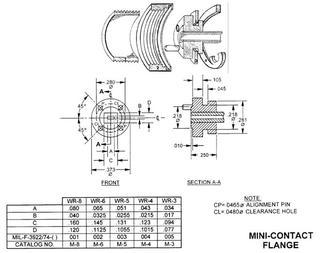
- CMR (Contact, miniature, unpressurizable, rectangular) = UER: Gaskets not
used. Available with three different types of attachment hole patterns - all
tapped holes, alternate tapped/clearance holes, and all clearance holes. UER
(IEC version) has all clearance holes.
- PDR (IEC designation): PDR contact flanges
require gaskets different from those for CPR because of deeper gasket grooves.
There are also small tolerance and hardware differences but PDR and CPR flanges
can be mated.
2. Flanges for Pressurization
1) Pressure flange
- Used in waveguide pressurization. VSWR < 1.1, 15 psi,
1/8" Schrader inlet valve

2) Flange with pressure window
- Window materials:
-
Teflon
-
Fiberglass
-
Kapton: high-temperature capability.
-
Mica
-
Ceramic: boron nitride (for high power applications)
- Fabrication: Dielectric materials are captivated within
the flange structure
- Allowable pressure: 30 psi
- Alumina ceramic:
For high-power RF window applications. Use of high quality
powder (grain size < 0.8 μm,
99.99% purity). Voids in the ceramic should be eliminated. Use of low RF loss
sintering binder materials. Micro-voids between grain boundaries and large
amounts of magnesium (Mg) are the main reasons for the discharge breakdown.
3. Flange Gaskets
1) Construction Materials
- Conductive silicone
 (EMF/RFI
gasket)
(EMF/RFI
gasket)  (O-ring
gasket for choke flange)
(O-ring
gasket for choke flange)
 (CPRG
full gasket)
(CPRG
full gasket)  (CPRG
half gasket)
(CPRG
half gasket)
 (Pressure
gasket)
(Pressure
gasket)
4. Flange Dimensions
1) Summarized data
H, X, M, P, N, K, R Bands:

Drill Sizes and Decimal Equivalents
(source: Cobham catalog)
Machine-Screw Dimensions (Source: Cobham catalog)
Flange Specifications (source: Cobham catalog)
Double Ridge Waveguide Specifications (source: Cobham
catalog)
Waveguide Power Handling vs. Pressure (source: Cobham catalog)
(Note)
1 atm = 760 mmHg = 760 Torr = 14.70 psi = 1.06 ton/ft2
= 1.033 kg/cm2 = 33.9 ft H2O
Flange Drawing (WR-19) (source: Cobham calalog)
Flange Drawing (WR-22) (source: Cobham calalog)
Flange Drawing (WR-28) (source: Cobham calalog)

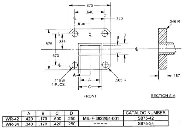
Flange Drawing (WR-34) (source: Cobham calalog)


CMR-90
CPRF-90

CPRG-90
Altitude De-Rating of Waveguide
Flexible Waveguides
Materials of construction: brass, beryllium copper,
silver-plated brass, silver-plated beryllium copper
Waveguide-Flange
Connection Methods
 (Thru)
 (Butt
= Corral thru)
(Butt
= Corral thru)  (Butt
socket)
(Butt
socket)
 (Butt corral)
GLOSSARY
MPRWG (metal pipe rectangular waveguide)
Rectangular Waveguides for THz
FEATURES and
APPLICATIONS
Features
Applications
MODAL FIELDS
Fig. The coordinate system for the
waveguide analysis [1].
TEmn modes


TMmn modes


Dominant TE10 Mode
1. Formulas and Equations


Let  for the maximum
power transfer before breakdown.
for the maximum
power transfer before breakdown.


2. Recommended Frequency Range of Operation
Cut-off frequency:

Recommended operating frequency
range:
 (commercial
waveguides)
(commercial
waveguides)
 (waveguide components)

Example: WR-10,  ,
,  ,
, 
3. Current on
Waveguide Walls
- On side walls: Current in transverse direction.
Vertical slot provides no perturbation.
- On the center line of broad walls: Current in waveguide
axis direction. Axial slot incurs no effect.
- Consideration of current flow is important in designing
radiating and coupling slots and waveguide mating devices.
Modal Field Distribution
Fig. Field
distribution of the rectangular waveguide modes.
CUT-OFF FREQUENCIES
ATTENUATION
Fig. The attenuation in the rectangular waveguide [1].
MODE CONVERTER
COMMERCIAL RECTANGULAR
WAVEGUIDES
|
Designation
|
Inner
dimension
a x b (mm)
|
a, b
tolerances
(mm)
|
Max.
inner
radius
(mm)
|
Wall
thickness
(mm)
|
Series A
TE10 mode
operating
frequency
(GHz)
(f1-f2)
|
Series B
TE10 mode
operating
frequency
(GHz)
(f1-f2)
|
TE10 mode
cutoff
frequency
(GHz)
|
Attenuation of
AL waveguide
(dB/30.5m)
(f1-f2)
|
b/a
|
Band
desig.
|
|
EIA
|
BS
|
IEC
|
|
WR
|
WG
|
R
|
|
2300
|
|
3
|
584.2×292.1
|
|
|
4.78
|
0.32 - 0.49
|
|
0.257
|
0.040-0.027
|
0.500
|
|
|
2100
|
|
4
|
533.4×266.7
|
|
|
4.78
|
0.35 - 0.53
|
|
0.281
|
0.046-0.031
|
0.500
|
|
|
1800
|
|
5
|
457.2×228.6
|
|
|
3.18
|
|
0.41 - 0.64
|
0.328
|
0.058-0.039
|
0.500
|
|
|
1500
|
|
6
|
381.0×190.5
|
±0.381
|
1.19
|
3.18
|
0.49 - 0.75
|
|
0.394
|
0.076-0.051
|
0.500
|
|
|
1150
|
|
8
|
292.1×146.1
|
±0.381
|
1.19
|
3.18
|
|
0.64 - 0.96
|
0.514
|
0.113-0.076
|
0.500
|
|
|
1000
|
|
|
353.4×123.8
|
|
1.19
|
|
0.75 - 1.10
|
|
|
|
0.489
|
|
|
975
|
|
9
|
247.7×123.8
|
|
1.19
|
3.18
|
0.75 - 1.12
|
|
0.606
|
0.145-0.098
|
0.500
|
|
|
770
|
|
12
|
195.5×97.79
|
±0.254
|
1.19
|
3.18
|
|
0.96 - 1.46
|
0.767
|
0.21-0.14
|
0.500
|
|
|
650
|
06
|
14
|
165.1×82.55
|
±0.127
|
1.19
|
2.03
|
1.12-1.70
|
|
0.908
|
0.27-0.18
|
0.500
|
|
|
510
|
|
18
|
129.5×64.77
|
±0.127
|
1.19
|
2.03
|
|
1.45-2.20
|
1.154
|
0.38-0.26
|
0.500
|
|
|
430
|
08
|
22
|
109.2×54.61
|
±0.127
|
1.19
|
2.03
|
1.70-2.60
|
|
1.375
|
0.50-0.33
|
0.500
|
|
|
340
|
09A
|
26
|
86.36×43.18
|
±0.127
|
1.19
|
2.03
|
|
2.20-3.30
|
1.737
|
0.68-0.47
|
0.512
|
|
|
284
|
10
|
32
|
72.14×34.04
|
±0.127
|
1.19
|
2.03
|
2.60-3.95
|
|
2.080
|
0.95-0.65
|
0.472
|
|
|
229
|
11A
|
40
|
58.17×29.21
|
±0.127
|
1.19
|
2.03
|
|
3.30-4.90
|
2.577
|
1.21-0.86
|
0.502
|
|
|
187
|
12
|
48
|
47.55×22.15
|
±0.127
|
0.79
|
1.63
|
3.95-5.85
|
|
3.155
|
1.79-1.24
|
0.466
|
|
|
159
|
13
|
58
|
40.39×20.19
|
±0.102
|
0.79
|
1.63
|
|
4.90-7.05
|
3.705
|
1.99-1.49
|
0.500
|
|
|
137
|
14
|
70
|
34.85×15.80
|
±0.102
|
0.79
|
1.63
|
5.85-8.20
|
|
4.285
|
2.53-2.00
|
0.453
|
|
|
112
|
15
|
84
|
28.50×12.62
|
±0.102
|
0.79
|
1.63
|
|
7.05-10.0
|
5.260
|
3.55-2.76
|
0.443
|
|
|
102
|
|
-
|
25.91×12.95
|
±0.076
|
0.79
|
1.63
|
7.0-11.0
|
|
5.787
|
4.27-2.89
|
0.500
|
|
|
90
|
16
|
100
|
22.86×10.16
|
±0.076
|
0.79
|
1.27
|
8.2-12.4
|
|
6.560
|
5.54-3.83
|
0.444
|
X
|
|
75
|
17
|
120
|
19.05×9.53
|
±0.076
|
0.79
|
1.27
|
|
10.0-15.0
|
7.847
|
6.55-4.58
|
0.500
|
|
|
62
|
18
|
140
|
15.80×7.90
|
±0.076
|
0.40
|
1.02
|
12.4-18.0
|
|
9.490
|
8.26-6.07
|
0.500
|
|
|
51
|
19
|
180
|
12.95×6.477
|
±0.064
|
0.40
|
1.02
|
|
15.0-22.0
|
11.54
|
11.3-8.17
|
0.500
|
|
|
42
|
20
|
220
|
10.67×4.318
|
±0.051
|
0.40
|
1.02
|
18.0-26.5
|
|
14.08
|
17.7-13.0
|
0.405
|
|
|
34
|
21
|
260
|
8.636×4.318
|
±0.051
|
0.40
|
1.02
|
|
22.0-33.0
|
17.28
|
21.6-15.0
|
0.500
|
|
|
28
|
22
|
320
|
7.112×3.556
|
±0.038
|
0.40
|
1.02
|
26.5-40.0
|
|
21.10
|
24.6-16.8
|
0.500
|
|
|
22
|
23
|
400
|
5.690×2.845
|
±0.025
|
0.25
|
1.02
|
|
33.0-50.0
|
26.35
|
34.5-23.5
|
0.500
|
Q
|
|
19
|
24
|
500
|
4.775×2.388
|
±0.025
|
0.25
|
1.02
|
40.0-60.0
|
|
30.69
|
38.0-27.3
|
0.500
|
U
|
|
15
|
25
|
620
|
3.759×1.880
|
±0.025
|
0.20
|
1.02
|
|
50.0-75.0
|
39.90
|
64.2-43.9
|
0.500
|
V
|
|
12
|
26
|
740
|
3.099×1.549
|
±0.013
|
0.15
|
1.02
|
60.0-90.0
|
|
48.40
|
87.8-58.9
|
0.500
|
E
|
|
10
|
27
|
900
|
2.540×1.270
|
±0.013
|
0.10
|
1.02
|
|
75.0-110
|
58.85
|
101-71.0
|
0.500
|
W
|
|
8
|
28
|
1200
|
2.032×1.016
|
±0.0076
|
0.051
|
0.51
|
90.0-140
|
|
73.84
|
154-98.7
|
0.500
|
|
|
6
|
29
|
1400
|
1.651×0.826
|
±0.0076
|
0.051
|
0.51
|
|
110-170
|
90.85
|
214-135
|
0.500
|
D
|
|
5
|
30
|
1800
|
1.295×0.648
|
±0.0076
|
0.051
|
0.51
|
140-220
|
|
115.8
|
308-194
|
0.500
|
G
|
|
4
|
31
|
2200
|
1.092×0.546
|
±0.0076
|
0.025
|
0.51
|
|
170-260
|
137.5
|
377-251
|
0.500
|
|
|
3
|
32
|
2600
|
0.864×0.432
|
±0.0076
|
0.025
|
Round
|
220-330
|
|
173.3
|
512-341
|
0.500
|
Y
|
|
(2.8)
|
|
|
0.711x0.356
|
|
|
|
|
260-400
|
|
|
0.500
|
|
|
(2.2)
|
|
|
0.559x0.279
|
|
|
|
330-500
|
|
|
|
0.500
|
|
|
(1.9)
|
|
|
0.483x0.241
|
|
|
|
|
400-600
|
|
|
0.500
|
|
|
(1.5)
|
|
|
0.381X0.181
|
|
|
|
500-750
|
|
|
|
0.500
|
|
|
(1.2)
|
|
|
0.305X0.152
|
|
|
|
|
600-900
|
|
|
0.500
|
|
|
(1.0)
|
|
|
0.254x0.127
|
|
|
|
750-1100
|
|
|
|
0.500
|
|
|
(0.80)
|
|
|
0.203X0.102
|
|
|
|
|
900-1400
|
|
|
0.500
|
|
|
(0.65)
|
|
|
0.165x0.083
|
|
|
|
1100-1700
|
|
|
|
0.500
|
|
|
(0.51)
|
|
|
0.130x0.065
|
|
|
|
|
1400-2200
|
|
|
0.500
|
|
Note:
1. Materials,
A=aluminum (1110 or 6061 alloy), B=brass, C=copper, S=silver
2.
Waveguide number with parentheses: (2.8) for example is from Virginia Diodes
Inc.
Note:
1.
Materials, A=aluminum (1110 or 6061 alloy), B=brass, C=copper, S=silver
2. Waveguide number
Rectangular Waveguide Flange
1.
Flange Designations
2. Flange Types
Standard Flange Data
Sources: 1. Maury Microwave Corp.
|
Waveguide
|
A(mm)
|
B(mm)
|
E(mm)
|
F(mm)
|
G(mm)
|
H(mm)
|
Hole diameter(mm)
|
|
WR-650
|
138.18
|
220.73
|
58.69
|
31.73
|
60.30
|
100.00
|
8.20
|
|
WR-430
|
106.38
|
161.04
|
43.69
|
23.83
|
45.39
|
70.99
|
6.71
|
|
WR-284
|
circular
flange
|
|
|
|
|
|
|
|
WR-229
|
70.20
|
98.73
|
26.67
|
12.70
|
27.18
|
41.15
|
6.50
|
|
WR-187
|
circular
flange
|
|
|
|
|
|
|
|
WR-159
|
61.98
|
80.77
|
22.35
|
9.53
|
12.70
|
32.26
|
6.50
|
|
WR-137
|
circular
flange
|
|
|
|
|
|
|
|
|
|
|
|
|
|
|
|
Square Cover Flange
a) Maury Microwave Corp.
|
Waveguide
|
A(mm)
|
E(mm)
|
F(mm)
|
Hole diameter(mm)
|
|
WR-112
|
47.90
|
18.72
|
17.17
|
4.255
|
|
WR-90
|
41.40
|
16.26
|
15.49
|
4.255
|
|
WR-75
|
38.30
|
14.25
|
13.21
|
4.085
|
|
WR-62
|
33.30
|
12.14
|
12.63
|
4.085
|
|
WR-51
|
33.27
|
12.62
|
12.14
|
3.658
|
|
WR-42
|
22.41
|
8.51
|
8.13
|
3.07
|
|
WR-34
|
22.41
|
8.51
|
8.13
|
3.07
|
|
WR-28
|
19.05
|
6.73
|
6.35
|
2.98
|
b) Quinstar Specifications
Square Choke Flange
1) Quinstar Specifications

Circular Cover Flange
1) Quinstar Specifications

2) Maury Microwave Inc. Specifications

|
Waveguide
|
A (mm)
|
Hole circle
dia.(mm)
|
Holes C
Type
|
Holes D
dia.(mm)
|
Dowels E
dia.(mm)
dowels
|
|
WR-22
|
28.55
|
23.81
|
4-40 UNC-2B
|
1.613
|
1.555
|
|
WR-19
|
28.55
|
23.81
|
4-40 UNC-2B
|
1.613
|
1.555
|
|
WR-15
|
19.05
|
14.29
|
4-40 UNC-2B
|
1.613
|
1.555
|
|
WR-12
|
19.05
|
14.29
|
4-40 UNC-2B
|
1.613
|
1.555
|
|
WR-10
|
19.05
|
14.29
|
4-40 UNC-2B
|
1.613
|
1.555
|
|
WR-8
|
19.05
|
14.29
|
4-40 UNC-2B
|
1.613
|
1.555
|
|
|
|
|
|
|
|
|
|
|
|
|
|
|
- Indexing:
- 2 index
pins: press-fit
- 4-pin
indexing pattern
- Raised boss in the center
- Existing design and problems: WR-22 for an example
- Cocking of mated flanges: Bolts outside the raised boss area. It is very
difficult to get a perfectly flat connection.
- Fixed index pin: Flange surface is unserviceable when it gets rough. Flange
surface needs to be lapped back to a smooth surface at regular intervals.
- Poor repeatability: Due to too much hole clearances for index pin and
cocking of the mated flanges.
- Poor index pin design: Fixed pin requires a lot of extra clearance to allow
for the worst-case tolerance conditions. Index pin placed at 45-degree location
leads to difficulties in placing it and checking the accuracy of the location.
Improved
Design
- Improved indexing schemes:
-
Two index holes in waveguide center line: Greatly improves the precision in
both fabrication and inspection.
-
Index pins are slip-fit type. Index pin is not installed in fixed position so
that it does not complicate
tolerance problems in mating.
- Raised outer edge: Prevent
cocking. Saves connection time. Makes lapping easier.
- Smaller-diameter boss at
waveguide center: Increased pressure on the mating surfaces.
- Can be made compatible with
existing standards.
Circular Flange, Pin-Contacted, Threaded Ring
1) Quinstar Inc. Specifications

(Figure from Space Machine & Engineering Corp.)
Waveguide Flanges - North American Types
Contact grooved:
CPR (Contact Pressurized Rectangular):

Square Cover:

Round Cover:

|
분류번호
|
형태
|
치수 데이터
(mm)
|
|
EIA
|
BS
|
IEC
|
|
WR
|
WG
|
R
|
|
2300
|
|
3
|
|
|
|
2100
|
|
4
|
|
|
|
1800
|
|
5
|
|
|
|
1500
|
|
6
|
|
|
|
1150
|
|
8
|
|
|
|
975
|
|
9
|
|
|
|
770
|
|
12
|
|
|
|
650
|
06
|
14
|
2
|
A=138.90, B=221.50, E=58.69, F=31.73,
G=60.30, H=100.00, Ø=8.20
|
|
510
|
|
18
|
2
|
|
|
430
|
08
|
22
|
|
A=106.38, B=161.14, E=43.69, F=23.83,
G=45.39, H=70.00, Ø=6.71
|
|
340
|
09A
|
26
|
|
|
|
284
|
10
|
32
|
|
|
|
229
|
11A
|
40
|
|
A=70.20, B=98.73, E=26.67, F=12.70,
G=27.18, H=41.15, Ø=6.50
|
|
187
|
12
|
48
|
|
|
|
159
|
13
|
58
|
|
|
|
137
|
14
|
70
|
|
|
|
112
|
15
|
84
|
3
|
C=47.90, D=18.72, E=17.17, 구멍직경=4.255
플레인지 가로(=세로)=47.90mm, 가로 구멍간격=34.34mm,
세로 구멍간격=37.441mm, 구멍직경=4.26mm, 두께=
|
|
102
|
|
-
|
|
|
|
90
|
16
|
100
|
4-hole
정사각형
|
UG-39/U
플레인지 가로(=세로)=41.40mm, 가로 구멍간격=30.99mm,
세로 구멍간격=32.51mm, 구멍직경=4.37mm, 두께=
|
|
75
|
17
|
120
|
4-hole
정사각형
|
플레인지 가로(=세로)=38.10mm, 가로 구멍간격=26.42mm,
세로 구멍간격=28.50mm, 구멍직경=3.73mm, 두께=
|
|
62
|
18
|
140
|
4-hole
정사각형
|
UG-419/U
플레인지 가로(=세로)=33.32mm, 가로 구멍간격=25.25mm,
세로 구멍간격=24.28mm, 구멍직경=3.73mm, 두께=
|
|
51
|
19
|
180
|
4-hole
정사각형
|
플레인지 가로(=세로)=31.00mm, 가로 구멍간격=20.58mm,
세로 구멍간격=22.50mm, 구멍직경=4.085mm
|
|
42
|
20
|
220
|
4-hole
정사각형
|
UG-383/U
UG-595/U:
플레인지 가로(=세로)=22.23mm, 가로 구멍간격=16.26mm,
세로 구멍간격 =17.02mm, 구멍직경=2.95mm, 두께=4.75mm
|
|
34
|
21
|
260
|
4-hole
정사각형
|
UG-383/U
UG-595/U:
플레인지 가로(=세로)=22.23mm, 가로 구멍간격=16.26mm,
세로 구멍간격 =17.02mm, 구멍직경=2.95mm, 두께=4.75mm
|
|
28
|
22
|
320
|
4-hole
정사각형
|
UG-599/U:
플레인지 가로(=세로)=19.05mm, 가로 구멍간격=12.70mm,
세로 구멍간격 =13.46mm, 구멍직경=2.95mm, 두께=4.83mm
|
|
8-hole 원형
|
UG-383/U
|
|
22
|
23
|
400
|
8-hole 원형
|
UG-383/U
|
|
19
|
24
|
500
|
8-hole 원형
|
UG-383/U
|
|
15
|
25
|
620
|
8-hole 원형
|
UG-387/U
|
|
12
|
26
|
740
|
8-hole 원형
|
UG-387/U
|
|
10
|
27
|
900
|
8-hole 원형
|
UG-387/U
|
|
8
|
28
|
1200
|
8-hole 원형
|
UG-287/U
|
|
4-hole 원형
|
TRG-714/U
|
|
7
|
|
1400
|
8-hole 원형
|
UG-387/U
|
|
4-hole 원형
|
TRG-714/U
|
|
5
|
|
1800
|
8-hole 원형
|
UG-387/U
|
|
4-hole 원형
|
TRG-714/U
|
|
4
|
|
2200
|
8-hole 원형
|
UG-387/U
|
|
4-hole 원형
|
TRG-714/U
|
|
3
|
|
2600
|
8-hole 원형
|
UG-387/U
|
|
4-hole 원형
|
TRG-714/U
|

2. 사각형도파관 플레인지 형태
2) Flange Type 2 (UDR Series Flange)

3) Flange Type 3 (UBR Series Flange)


4)
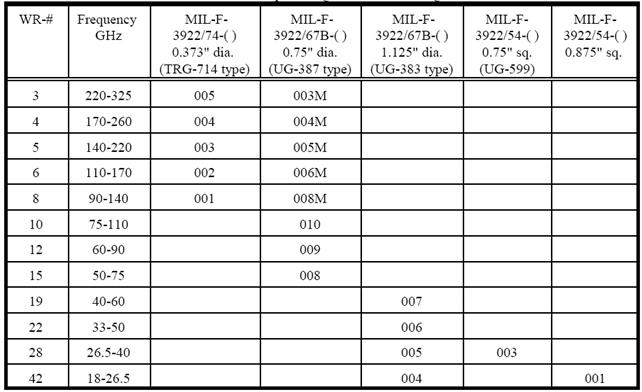
Flange Type 4 (UG-38x/U Series, MIL-F-3922/67B-xxx Series)
TRG-714
: 플레인지 UG-387 : 플레인지
UG-383 :
플레인지
밀리미터파대역
플레인지
1) 요약표
|
Type
|
최외각 형태 및 크기
|
두께(mm)
|
|
UG-595/U
|
정사각형 22.225mm (0.875")
|
4.826mm (0.190")
|
|
UG-599/U
|
정사각형 19.050mm (0.750")
|
4.826mm (0.190")
|
|
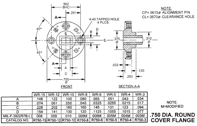
UG-383/U
|
원형 직경 28.575mm (1.125")
|
3.302mm (0.130")
|
|
UG-385/U
|
|
|
|
UG-387/U
|
원형 직경 19.050mm (0.750")
|
3.302mm (0.130")
|
|
TRG-714/U
|
원형 직경 9.747mm (0.388")
|
Not applicable
|
|
|
|
|
|
|
|
|
|
|
|
|
① TRG-714 플레인지 (Mini-contact flange): 직경 9.474 mm (0.383")
- 90GHz 이상의 주파수에서도 TRG-714 플레인지보다도 UG-387 플레인지가 더 많이 사용됨.
-
TRG-714 플레인지의 결합방법을 도파관 부품 (예, 믹서 블록)에 적용하기 곤란함.
- 결합 오차: 0.0032" maximum lateral misalignment
②
UG-387 플레인지:
직경
19.050 mm (0.75")
가. 표준형
플레인지 도면
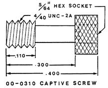
Flange Screw
- 플레인지에 항상 볼트가 장착되어 있도록
captive screw가
사용됨.
- 나사산(thread)가 없는 부분:
직경
0.078" +0/-0.002"
- Recommended seating
torque: 5 in-lb typ., 8 in-lb max.
- 재질:
스테인레스
스틸
(303, 305 type)
- Screw tap 규격:
#4-40 UNC 2A
플레인지 조립 정밀도(alignment
accuracy)
- Alignment pin (dowel)의 정확도(핀위치,
핀직경,
핀구멍
위치,
핀구멍
직경)에 의해 결정됨.
- W-대역
(75-110GHz)에서
0.006", 0.003"의
결합오차가
있을
경우
플레인지
접합부에
의한
반사계수는
각각
-23dB와
-35dB이다.
- Alignment pin 종단은 반구면 형상으로 한다.
|
규격/회사
|
정렬핀 구멍 공차
|
정렬핀 위치 공차
|
정렬핀 직경
|
정렬핀 구멍 직경
|
최대 결합오차
|
|
MIL Spec.
Aerowave
Custom
Microwave
M/A-Com
|
0.001"
|
0.0015"
|
0.0615"
|
0.0670"
|
0.008"->
0.006"
|
|
Militech
|
|
|
0.0635"
|
0.0650"
|
|
|
Agilent
|
|
|
0.0630"
|
0.0654"
|
0.0049"
-> 0.003"
|
|
Hughes, NRAO
|
|
|
0.0615"
|
0.0635"
|
|
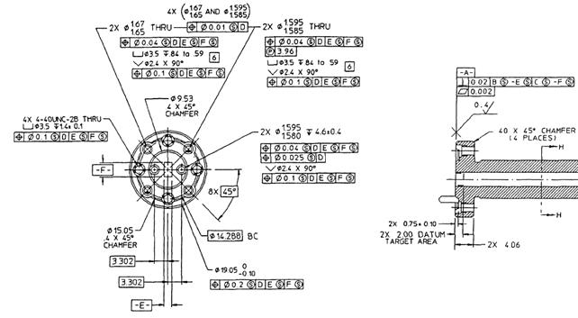
나. Anti-cocking 형
UG-387/U와 같은 플레인지는 도파관 주변이 원형으로 조금 더 튀어 나오게 하여
(central boss) 4개의
screw를
균등한
힘으로
조이지
않을
경우
아래
그림에서와
같이
screw가
설치된
면이
접촉되지
않는
관계로
한쪽이
더
많이
조여지는
현상(cocking)
이
발생한다.

Cocking
현상을
방지하기
위해
아래
그림과
같이
central boss를
제거한
anti-cocking flat flange가
사용된다.
(Anritsu, Agilent, Flann 사
등)


아래
그림은
Agilent사의
도파관
calibration 부품에
사용되는
anti-cocking 플레인지
도면이다.
Alignment 핀의
위치와
alignment용
구멍의
오차가
MIL Spec.보다
작아서
도파관
결합시
최대
오차가
0.003"(0.0762mm) 발생할
수
있다.
내부에
추가로
설치한
정렬핀에
의해
연결
정확도가
개선되지는
않는다.
외부
정렬핀
구멍이
마모로
오차가
증가할
경우
내부
정렬핀을
사용할
수
있다.
③
UG-383 플레인지:
직경
28.575 mm (1.125")

④
UBR Flanges : 0.750" square flange (UG-599/U), 0.875" square flange
- 표준형:
정렬핀이
없음.
- 개선형:
정렬핀이
있음.


5) Flange Type 5


6) Other Flange Types
- UAR Flange

- 5985-99-083

3. 사각형 도파관 플레인지 기술정보
두 도파관을 연결하는 부품을 플레인지라 한다. 플레인지는 압축형/비압축형, 초우크형/비초우크형 등으로 분류된다. 플레인지의 단면 모양은 도파관의 크기에 따라 사각형(저밀리미터파 대역 이하에서) 또는 원형(저밀리미터파 이상 주파수에서)이며 두 개의 플레인지를 연결하기 위한 구멍이 플레인지 가장자리에 배치된다. 구멍에는 나사산이 있는 경우도 있으며 없는 경우도 있다.
플레인지의 규격으로 EIA(Electronic Industry Association), MIL(U.S.
Military), IEC(Interational Electrotechnical Commission) 등이 있다. 세 규격은 상호 호환성을 가지지만 동일하지는 않다. 규격의 차이는 보통 공칭치수상상의 미소한 차이, 공차, 스캣의 형태 및 두께, 정밀결합용(alignment) 핀/구멍/ 볼트의 추가 또는 생략 등에 있다.
1) 비가압형 플레인지
CMR, UER 형 contact 플레인지는 비가압형이다. 사각형인 CMR 플레인지에는 나사산이 있는 구멍과 나사산이 없는 구멍이 교대로 있으며 너트를 사용하지 않고 볼트만을 사용하여 연결된다. IEC 규격 플레인지에는 나사산이 없는 구멍만이 있으며 두 플레인지는 너트와 볼트로 체결된다.
2) 가압형 플레인지
2.1) 초우크(choke)플레인지
CBR, CAR 및 이와 동등한 UG 형이 이에 속하며 개스킷 홈, 초우크 홈과 나사산이 있는 구멍 등이 나 있다. 초우크 플레인지는 커버 플레인지와 결합되며 초우크 플레인지와는 결합되지 않는다.
2.2) 커버(cover) 플레인지
UBR, UAR, UG 형 플레인지. 개스킷 홈이나 초우크 홈이 없으며 나사산이 없는 구멍이 있다. 초우크 플레인지와 커버 플레인지와 결합될 수 있다. 두 개의 커버 플레인지를 결합할 때 특별한 개스킷을 사용하면 내부에 압축기체를 넣을 수 있으며 방수기능을 가지게 할 수 있다.
REFERENCES
[1] D. M. Pozar, Microwave
Engineering, Second Edition, New York: John Wiley & Sons, 1998.