Handbook for Basics
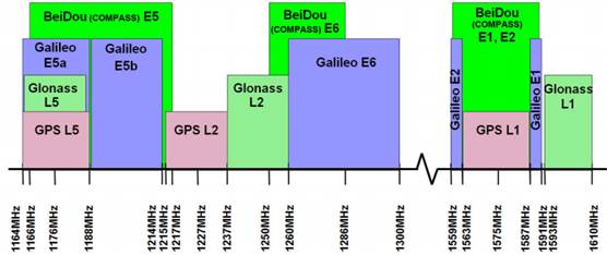
[GNSS+Satellite phone
(GMSS)
-
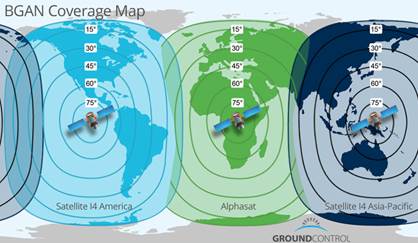
GMSS: Inmarsat, Globalstart, Iridium, Thuraya
-
Inmarsat BGAN coverage:
|
서비스명 |
주파수(MHz) |
편파 |
|
Iridium |
1621-1627 |
RHCP |
|
Inmarsat |
1525-1661 |
RHCP |
|
Thuraya |
1525-1661 |
LHCP |
|
Globalstar |
1610-2500 |
LHCP |
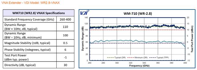
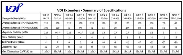
[THz VNA Performance
1. VDI
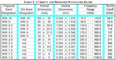
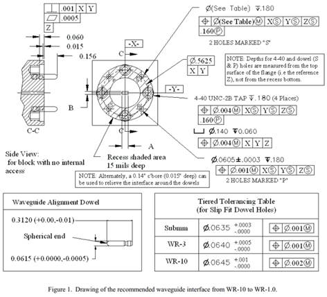
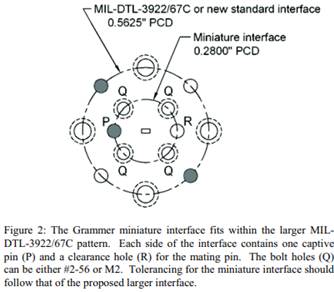
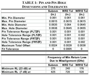
[Millimeter-Band Rectangular Waveguides
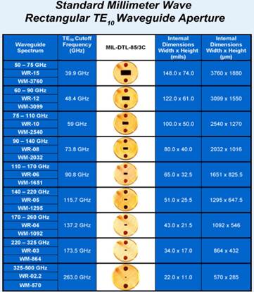
- N.M. Riddler,
"Towards standardized waveguide sizes and interfaces for submillimeter
wavelengths"
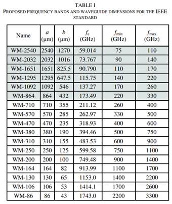
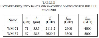
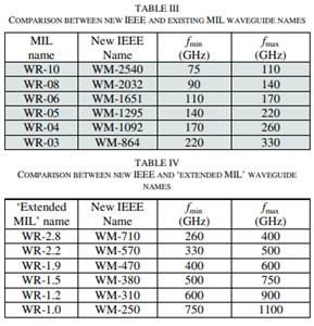
- J.L. Hesler,
"Recommendations for waveguide interfaces to 1 THz"
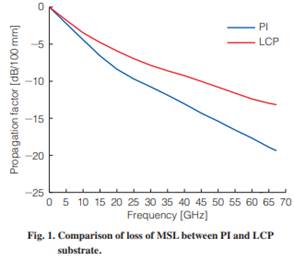
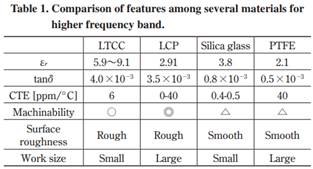
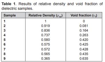
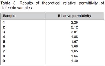
[Low-Loss Dielectric Mateirals
R. Hosono, "Development of LCP-based
millimeter-wave devices", Fujikura Tech. Rev., 2018
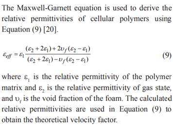
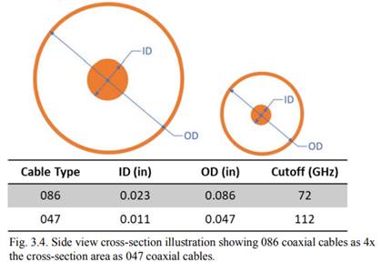
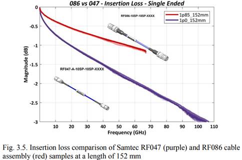
[Coaxial Cable Loss
M. Moradian, "Investigating the effect of foam
properties on the attenuation of coaxial cables with foamed polyethylene
dielectric,"
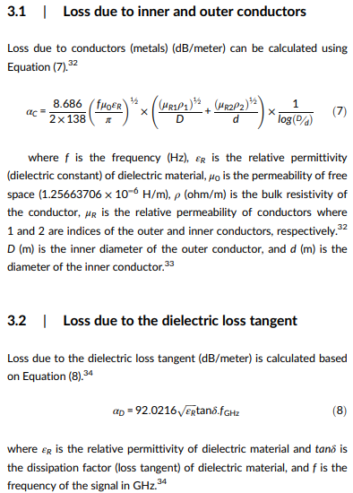
2. Foam dielectric-filled coax
M. Moradian, "Changes in signal transmission
speed in coaxial cables through regulating the foam structure of the
polyethylene dielectric section," Polyolefins Jour., 8(1), 2021.
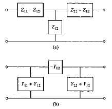
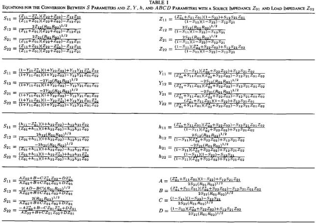
[Microwave Network Theory
1. Network Parameter
Convertion
- D.M. Pozar, Microwave Engineering 4e, 2012.
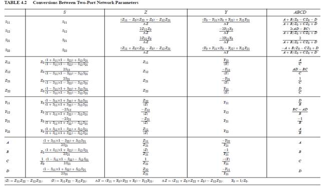
2. D.A. Frickey,
"Conversions between S, Z, Y, h, ABCD and T parameters which are valid for
complex source and load impedances", IEEE T-MTT, 43(1994).
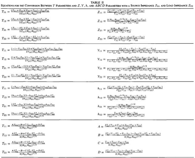
3. P. Miazga,
"Generalized linear network analysis method based on the transfer
scattering approach," IEEE T-MTT, 72(2024).
[Coaxial Connectors
1. B. Gore, "Are 1.0
mm precision RF connectors really required for 224 Gbps PAM4
verification?" DesignCon 2024.
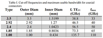
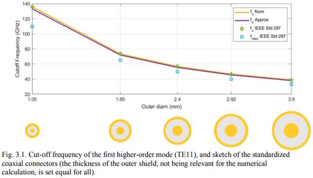
- Coaxial cable velocity
factor: 0.7-0.8 = 1/√εr
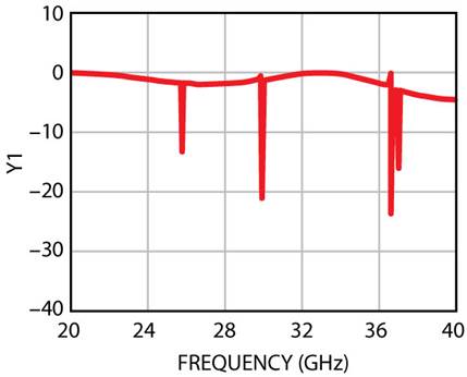
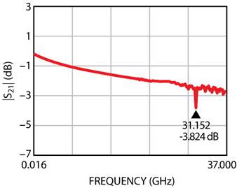
- Discontinuity-induced TE11-mode
resonance
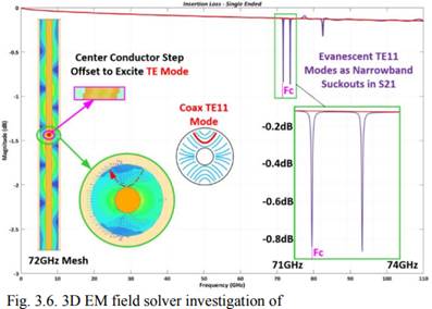 (086 cable, 20 mm)
Modal impedance
discontinuity
Insertion loss plot shows a
narrow band resonance peak at the cutoff frequency
2. B. Williams,
"Overmoding transission characteristics of Type-N connector 7mm line
between 18 and 26.5 GHz," ANAMET Report 044, 2004.
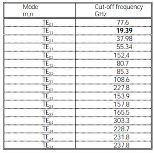
- 7mm coaxial cable cutoff
frequencies

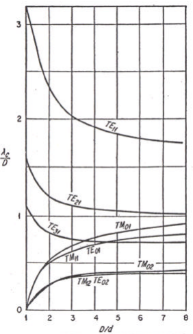
- Cutoff wavelength vs D/d
- TE11 mode cutoff formula
![]()
c = 2.3026, m=1, (c
+ 1)χ11 = 2.0413
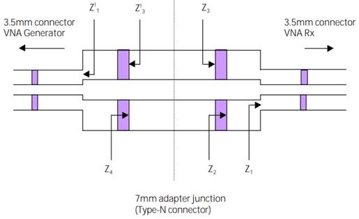
- Adapter insertion loss
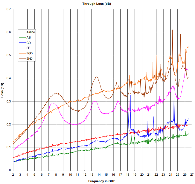
Bead resonance spike
between 18 and 19 GHz, 20.9, 21.8, 24.5 GHz
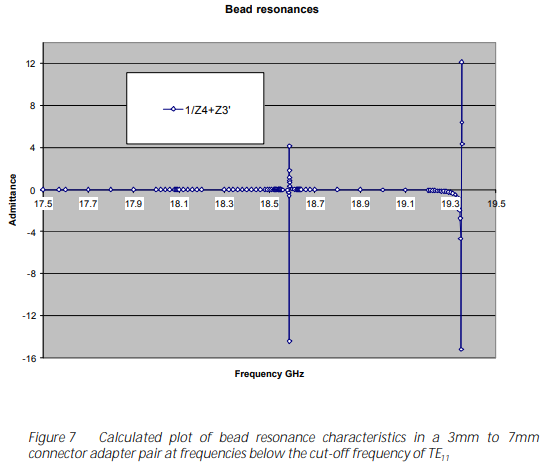
See, J F Gilmore, "TE11 mode resonances in precision coaxial connectors," General Radio Experimeter, pp 10 – 13, August 1966.
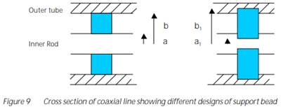
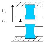
- Conujate match condition → Bead resonance
- Bead dielectric, TE11 mode above 14.47 GHz, bead width 2 mm, wavelength in dielectric at 15 GHz 2cm.
- Input impedance to the left of the bead: Presents a conjugate match to the right.
- This will generate TE11 mode in the bead but will be cutoff in the air-filled line.
- This is sometimes referred to as a 'ghost mode' in the world of dielectric measurement.
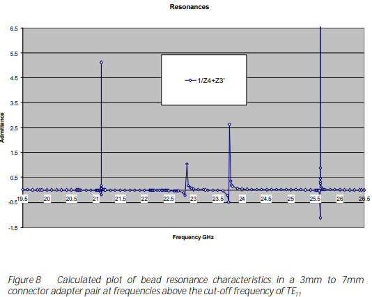
- The above was investigated, from 14 to 19.5 GHz, by calculating the impedance either side of a particular bead support. Results are given in Figure 7, below, where the reciprocal of the sum of the impedance, either side of a bead is plotted against frequency.
- The calculations are sensitive to dimensions, in particular, the width of the bead and the dielectric constant (relative permittivity).
- The big question is if the spikes represent the TE11 resonating within the bead, why does it not continue to propagate and cause more pronounced effects above the cutoff?
- Reflection coefficient
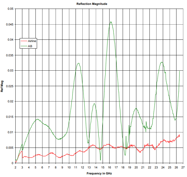
- Bead support structure
3. Extended-freqncy SMA
connectors
R. Fuks, "SMA
connectors with extended frequency range," Microw. J., 2007
- Designed in late 1950s
for 0.141" semi-rigid cable. Max. freq. 12 GHz (initial)
- Design maturized for 18
GHz limit
- Compatible with 3.5 mm
(36 GHz max.), 2.9 mm (SMK, 46 GHz max.) connectors
- TE11 mode cutoff
fc = 7.514/[(D+d)√εr]
(GHz), D and d in inches
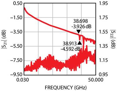
HFSS simulation: SMA,
contact diameter 0.050", Teflon diameter 0.1625"
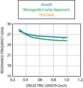
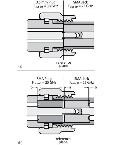
- Premer SMA connector:
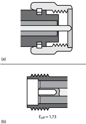
Designed by Astrolab, 27 GHz max., Bead effective dielectric constant 1.73
 Thick-wall SMA plug connectors
 Connection between thick wall SMA plug and Premier
SMA jack
Connection between thick wall SMA plug and Premier
SMA jack
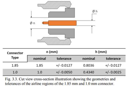
4. "The importance and
role of RF coaxial connector pin height and its impact on electrical and
mechanical performance"
Mating interface: For
mating male and female connectors. Polarized (male, female)
Contact: Center conductor
in a connector. Pin (mating pin; male contact) and socket (female contact;
spring fingered; heat treated beryllium copper) configuration
Female connector
Male connector
Pin height (=length);
Mating pin has a shoulder
Connector reference planes:
Best performance with the smallest gap between the pin shoulder and the socket
end.
Pin mating (or contact)
gap: At high frequencies, it causes reflection
Pin tip: Has a
characterized taper
SMA connector
TNC connector
N connector
QMA connector
Connector interface
Connector guaging
requirements: dimensions
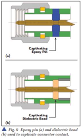
Captivated contacts
Non-captive contacts
Captivation methods: To
hold center conductor within a connector; Epoxy, dielectric beads (machined or
molded; PEEK, Ultem, Torlon, Vespel; high strength with good dielectric
properties)
5. B. Fernald, "Online
spotlight: RF connector selection guide," Microw. J.

[Circular Waveguide Modes
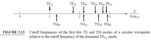
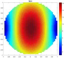
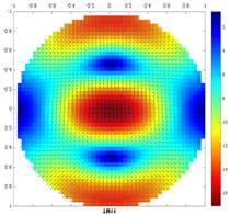


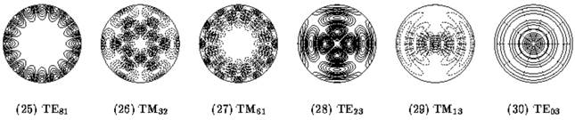
- TE11 mode and
easily-excited modes
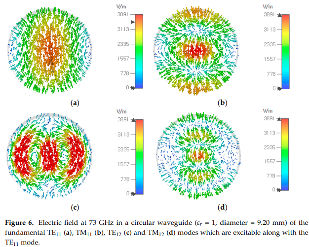
- Modes not excited along
with TE11 mode
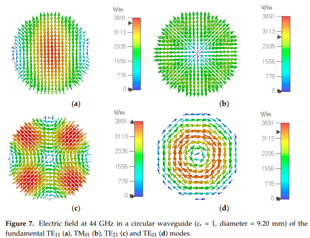
- Example:
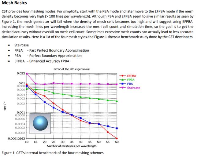
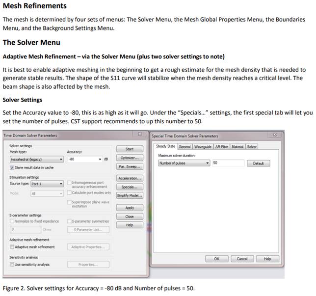
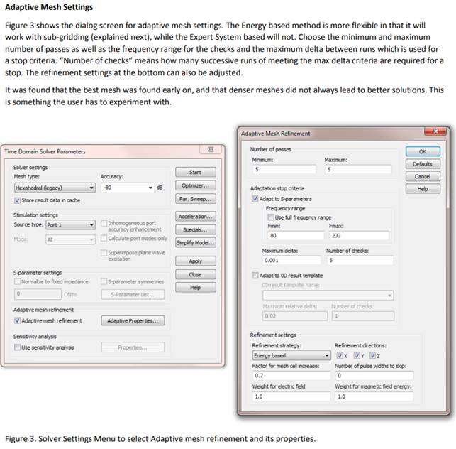
[CST Studio Suite
1. High Accuracy Simulation
- Meshing Modes: Use EFPBA
https://loco.lab.asu.edu/loco-memos/edges_reports/tom_20141111_part2.pdf
- Adaptive Mesh Refinements
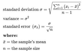
[Error Statistics
- Standard
deviation (SD) measures the dispersion of a dataset relative to its mean.
- The standard
error of the mean (SEM) measures how much discrepancy is likely in a sample's
mean compared with the population mean.
[Cutoff Frequency,
Waveguide
- Rectangular Waveguide
![]()
[Guided Wavelength
![]()
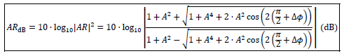
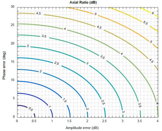
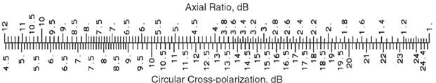
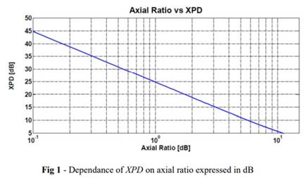
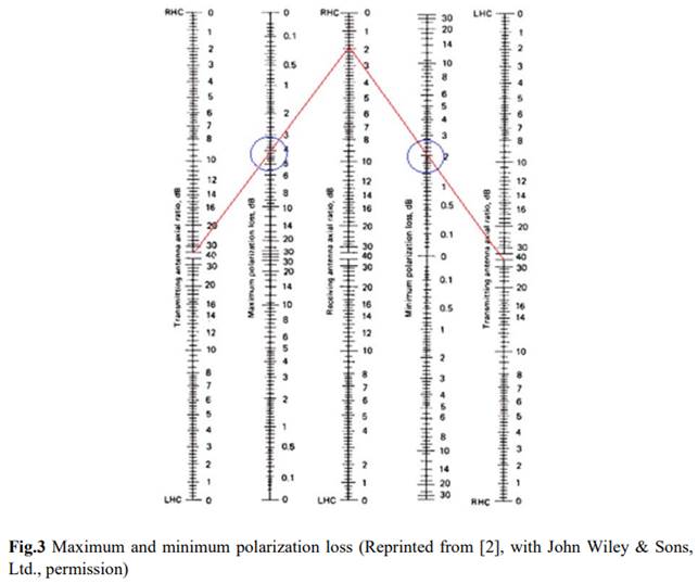
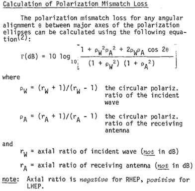
[Polarization
Ref: Linear to circular polarization conversion using microwave hybrids
for VGOS (2-14 GHz)
![]()
![]()
![]()
https://forum.amsat-dl.org/cms/index.php?file-download/4225/
https://ieeexplore.ieee.org/document/6086096
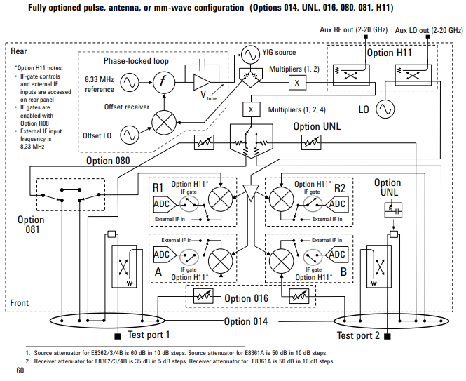
[VNA Block Diagram &
Performance
- Agilent PNA Microwave
Network Analyzer: 10MHz - 20, 40, 50, 67 GHz ; E8362B, E83363B, E8364B, E8361A
Ref: https://www.keysight.com/us/en/assets/7018-08817/data-sheets-archived/5988-7988.pdf

[Determinant of a Matrix
When calculating a matrix determinant using cofactor expansion, you can choose to expand along any row or column of the matrix.
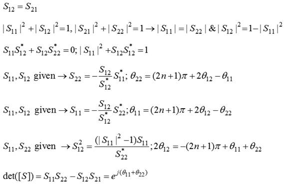
[Lossless Reciprocal
Two-Port
- Ref
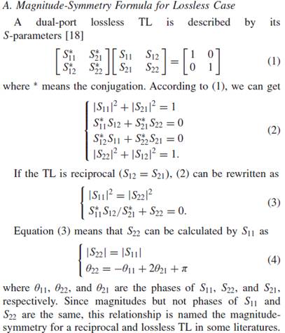
- Ahn
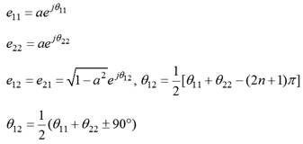
|
S11
= 0.1 (20°), S22 = 0.1 (30°), S21 = 0.995(70°) S11
= 0.2 (20°), S22 = 0.2 (-20°), S21 = 0.9798(45°) -
Ref: Amakawa, on the choice of cascade de-embedding methods ...
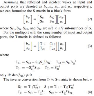
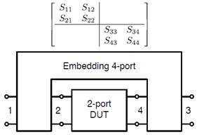
The most general
description of a 2-port de-embedding problem involves a 4-port as the mbedding network (Fig. 1). |
- Ref: H. J. Eul,
experimental results of new self-calibration procedures ...
The calibration of
network analyzers at their measurement ports is common to enhance measurement
accuracy. A well known method is the 12-Term procedure [1], [2]. As it employs
the standards Thru, Match, Short and Open, it is sometimes called TMSO procedure.
In contrast to other procedures
[3] (TSD = Thru,
Short, Delay) and [4] (TRL = Thru, Reflect, Line) the 12-Term procedure only
depends on fully known standards.
While having the
advantage of employing partly unknown standards, TRL and TSD have the shortcomming
that the electrical length of the line must be different from multiples of the
half-wavelength, resulting in a lower bandlimit and periodically repeating
frequency ranges of poor performance.
A family of new
self-calibration procedures is proposed in [6] allowing for a higher number of
unknown parameters in the standards.
The drawback of
TRL and the TSD, the limited bandwidth, has been overcome
with the xAx- and
xMx-types, since they are on principle of unlimited bandwidth.
Based on a general
theory for network analyzer calibration two families of calibration
procedures have
been presented, actually the Txx-procedures (TAN, TAR, TAS, TLN,TLR, TLS, TMN,
TMR, and TMS) and the corresponding Lxx-procedures (LAN, LAR, LAS, LLN, LLR,
LLS, LMN, LMR, and LMS).
-
Hayden, an enhanced Line-Reflect-Reflect-Match calibration
When computing the LRRM calibration the system relies
on uniqueness of the reflect standards to provide information (equations) to
help solve for the error-terms (unknowns). A problem may be observed when using
probe tip reflect standards and the thru line is approximately one-quarter
wavelength long. At this frequency (and odd multiples) ideal open and shorts
located at the probe tip are contributing the same information, preventing a proper
cal (resonant spikes are observed on the open verification plot). The LRRM
algorithm is largely computed with a center-of thru reference plane.
Re-computing these (probe-tip) reflects for their apparent value at a
center-thru reference plane results in impedances with zero real part and
opposite sign imaginary part when the resonant spikes occur. It is apparent
from experimentation that the two reflects are providing the same information
in this situation. The solution to the system given by (13) and (19) is
singular and the denominator of (20) goes to zero.
-
Virone, Extended through-short-delay technique ...
Conversely, thru-reflection-line (TRL) and
through-short-delay (TSD) techniques are widely recognized as the most precise
means of calibration of VNAs with connectable waveguide ports since they fully
exploit the self-calibrating capabilities of the standards adopted in the
calibration process [8]. Moreover, multiple-line TRL methods can be adopted in
order to widen the bandwidth and to improve the accuracy of the calibration [9]
of single-mode and multimode VNAs [10].
- Degerstrom, US20110298476A1
Symmetric fixture
Thru, open/short
Thru-1, Thru-2
ABCD matrix, Levenberg-Marquardi optimization