Antenna Design
Lab 11 - Loop Antenna
I. Simulation
Design frequency: f 0 =
(1000 + PIN/10000) MHz; 실습조교 PIN
= 0000
Loop material: PEC
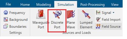
Source: discrete port
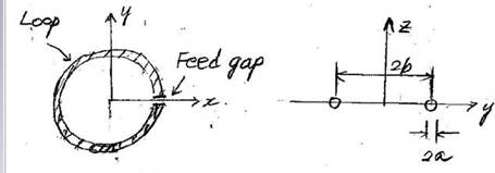
b = λ0 /
6 = 50 mm (λ0 = c / f0 )
a = b/50
= 1 mm
Feed gap = 2a
Simulation frequency range: Frequency range: 0.2f0 - 1.5f0
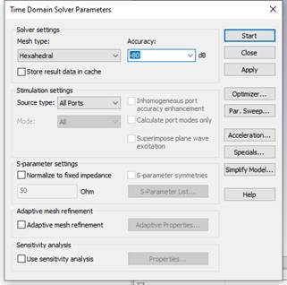
Solver: Time Domain Solver
Time Domain Solver Parameters: Accuracy = -80 dB
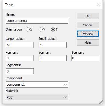
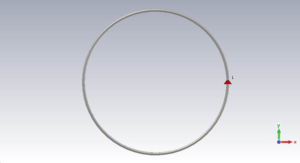
(1) Make the Loop antenna
Modeling, (Torus)
고리 아이콘 선택, ESC 키, Name:
solid1, Orientation: Z
Large radius:
51, Small radius: 49
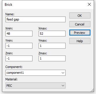
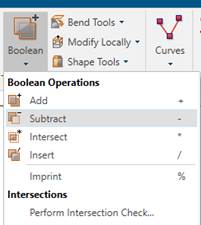
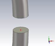
(2) Make the feed gap
Modeling, Brick
아이콘 선택, ESC 키, Name: solid2
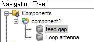
Navigation
Tree, Components, component1, Loop antenna 클릭
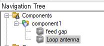
Modeling,
Boolean, Subtract, feed gap, 엔터키
3) 포트설정
Modeling, Pick
Points, Pick Face Center, gap 한면에 마우스 위치후 더블클릭
Pick Points,
Pick Face Center, gap 한면에 마우스 위치후 더블클릭
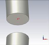
Simulation,
Discrete Port
4) 시뮬레이션 설정
주파수 설정:
Simulation,
Frequency, Min. frequency: 0.2, Max. frequency: 1.5
필드 모니터 설정:
Simulation,
Field Monitor, E-field, Frequency, Frequency:1, Apply
Simulation,
Field Monitor, H-field and Surface current, Frequency, Frequency:1, Apply
Simulation,
Field Monitor, Far field/RCS, Frequency, Frequency:1, Apply
메쉬 설정(메모리가 부족하거나, 학생버전에서):
Simulation,
Global Properties,
Cells
per wavelength: 5
Cells
per max model box edge: 5
Fraction
of maximum cell near to model: 5
5) 시뮬레이션
Simulation,
Setup Solver
Time Domain Solver Parameters: Accuracy = -80 dB
1. Plot the antenna structure
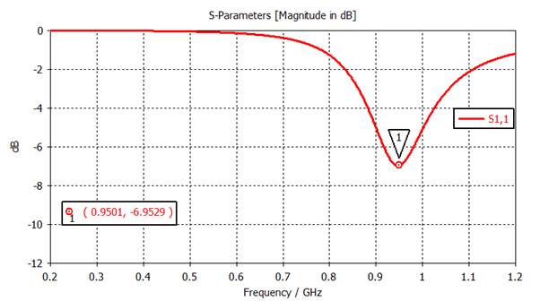
2. |S11| analysis
1) Plot |S11| (dB) at 0.2 - 1.2 GHz.
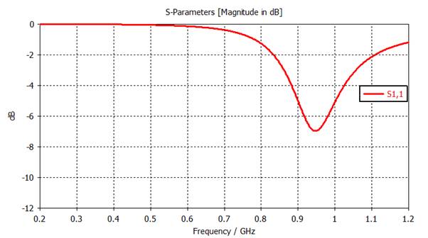
2) Find the frequency for minimum |S11|. It happens
when the loop circumference is one wavelength.
|S11| = |S11|min at f =
( 0.95 ) GHz
Right click, Add Curve Marker, place the mouse pointer
on the curve and double click
3) Plot S11 on the Smith chart. Mark the frequency f0 on
the S11 curve.
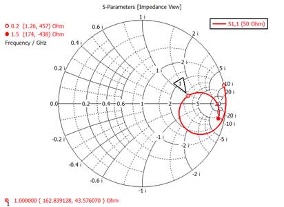
4) Find Z11 at f0.
Z11 =
(162.84 ) + j
( 43.57 ) Ω
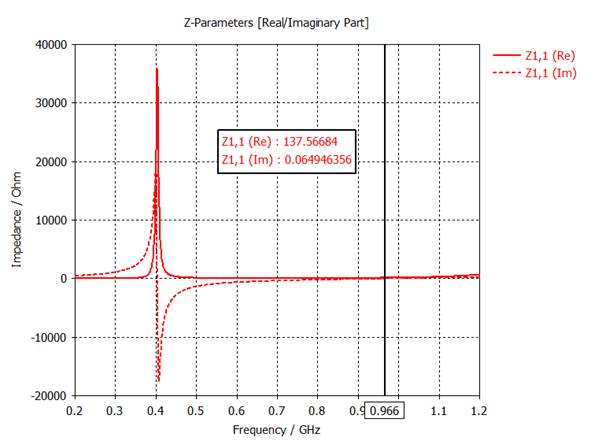
3. Z11 (Input impedance) analysis
1) Plot Re(Z11) and Im(Z11) on a same graph.
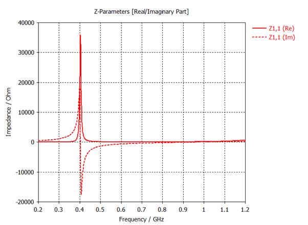
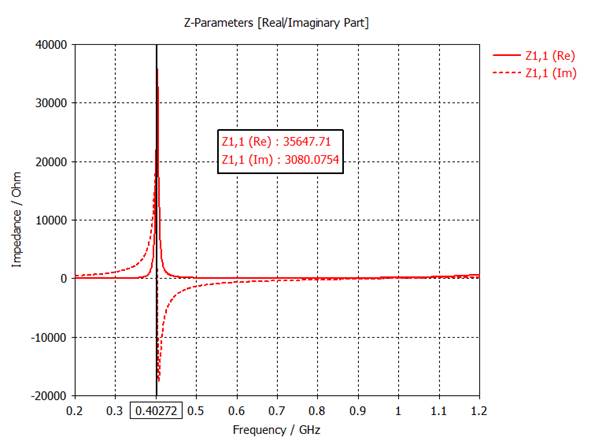
2) Find the first resonant frequency f1 where
the antenna can be modelled as a parallel resonant circuit. It happens when the
loop circumference is a half wavelength. Find Z11 at f1.
f1 =
( 0.402 ) GHz
Z11 = (35647) + j (0) Ω
3) Find the seconde resonant frequenc f2 where
the antenna can be modeled as a series resonant circuit. It happens when the
loop circumference is one wavelength. Find Z11 at f2.
f2 =
(0.966) GHz
Z11
= (137) + j ( 0) W
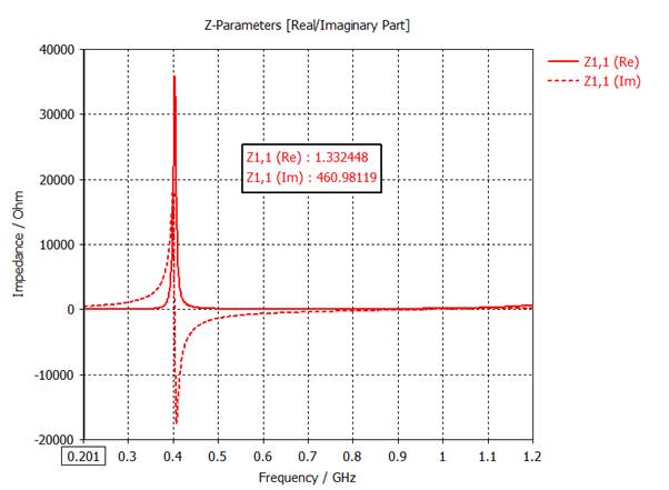
4. Find the small loop impedance
Z11 = ( 1.33) + j ( 461) W at
0.2f0.
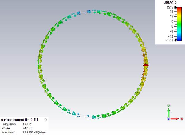
5. Check the current distribution on the loop antenna.
1) Plot the surface current on the loop at 0.5f0.
2) Plot the surface current on the loop at f0.
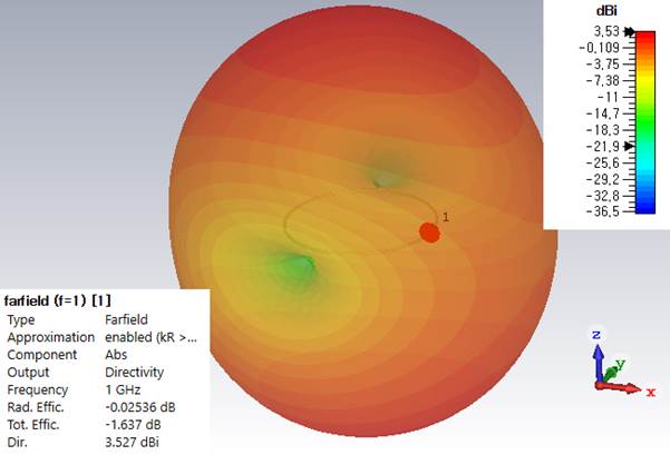
6. Investigate 3D far-field directivity patterns.
1) Dabs, Dtheta, Dphi at 0.5f0.
2) Dabs, Dtheta, Dphi at f0.
II. Discussions
1. Find the accurate resonant length and resistance of
a full-wavelength loop.
2. What is the directivity of a full-wavelength loop.