Antenna Design
Lab 13 - Small Antenna Impedance Matching
I. Simulation
Design frequency: f 0 = (300 + PIN/10000) MHz; 실습조교 PIN = 0000
Antenna material: copper
Source: discrete port
1.
Short Dipole and Impedance Matching
Wavelength: 1 m
Dipole length L: 0.1 wavelength
Wire diameter d: 0.001
wavelength
Feed gap g: 0.001 wavelength
Wire material: copper (conductivity 5.7 × 10⁷ S/m)
Simulation frequency range: 0.93 f0 - 1.07 f0 (280-320 MHz)
Impedance matching frequency: f0
(300 MHz)
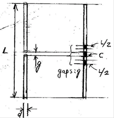
Figure: Left = a short dipole antenna, Right = Short dipole with matching
elements. Inductors L/2 are inserted
in the dipole wire while the capacitor C
is connected across the feed gap in parallel with the discrete port.
For the dipole antenna without matching elements,
1) plot the antenna geometry.
2) Plot S11 on the Smith chart.
3) Plot |S11|(dB) Cartesian.
4) Plot the real and imaginary parts of Z11.
5) Find the antenna input impedance Z11 at f0.
Z11 = (
) + j (
) W
For the dipole with matching elements,
6) Find the matching circuit element values (the first solution).
L = (
) uH
C = (
) pF
7) Add matching circuit elements and simulate the structure. Plot the
antenna geometry.
8) Plot S11 on the Smith chart.
9) Plot |S11|(dB) Cartesian after matching.
10) Find the 10-dB bandwidth
10-dB
bandwidth = (
) MHz
10-dB
bandwidth = (
) %
2. Small Loop and Impedance Matching
Wavelength: 1 m
Loop diameter D: 0.1 wavelength
Wire diameter d: 0.001
wavelength
Feed gap g: 0.001 wavelength
Wire material: Copper (conductivity 5.7 ×
107 S/m)
Simulation frequency range: 0.93 f0 - 1.07 f0 (280-320 MHz)
Impedance matching frequency: f0
(300 MHz)
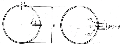
Figure: Left = a small loop, Right = a small loop antenna with matching elements.
Capacitors 2C1 are
inserted in the loop wire while the capacitor C2 is connected across the feed gap in parallel with the
discrete port.
For the small loop antenna without matching elements
1) Plot the antenna geometry.
2) Plot S11 on the Smith chart.
3) Plot |S11|(dB) Cartesian.
4) Plot the real and imaginary parts of Z11.
5) Find the antenna input impedance Z11 at f0.
Z11 = (
) + j (
) W
For the small loop antenna with matching elements
6) Find the matching circuit element values (the first solution).
C1 = (
) pF
C2 = (
) pF
7) Add matching circuit elements and simulate the structure. Plot the
antenna geometry.
8) Plot S11 on the Smith chart.
9) Plot |S11|(dB) Cartesian after matching.
10) Find the 10-dB bandwidth
10-dB
bandwidth = (
) MHz
10-dB
bandwidth = (
) %