IV. 실습 보고서
1. Two-element
Yagi antenna
Frequency:
300MHz(wavelength 1m)
Feed gap: 0.01
wavelength
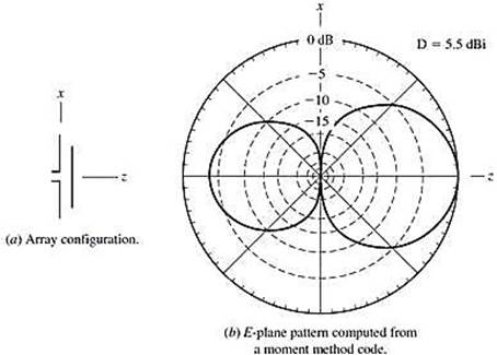
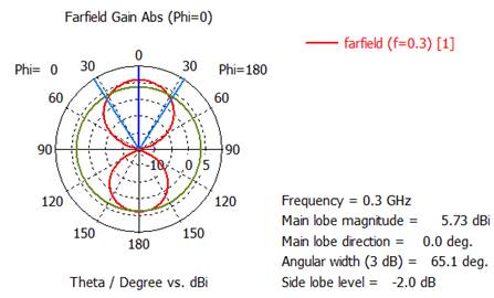
그림: 급전기와 지향기에 의한 방사패턴. 급전기 길이0.47λ, 급전기-지향기 간격0.20λ, 도선 직경0.01λ
For the director length of length 0.42
wavelength:
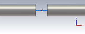
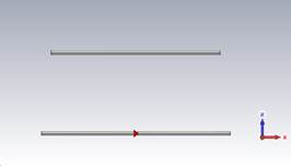
1) Plot the antenna geometry.
2) Plot the Dabs polar pattern on the E plane(zx-plane). Scale: max. 10dB, min. –15dB.
(해답)
1) Plot the
antenna geometry.
(1) Make a project template.
Project Template
New Template, Microwaves & RF /
Optical, Anennas
Create Project Template: Wire, Time Domain
Units: default(mm, GHz)
Frequency Min. : 0.09GHz
Frequency Max. : 0.6GHz
Monitors: E-field, H-field, Farfield
Defined at: 0.3GHz
Template name: Yagi antenna
Feed gap=
10mm
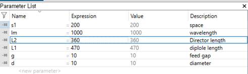
(2) Write the parameter
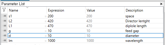
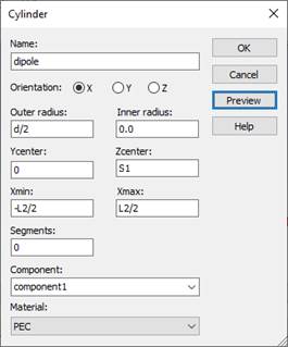
A. Make Dipole wire using
parameter symbols.
Modeling, Cylinder icon, ESC key, Name: solid1,
Orientation: x
Outer radius: d/2, Inner radius: 0
Y center:0 Z center:0
X min: -L1/2 X max : L1/2
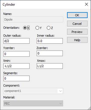
Material : PEC
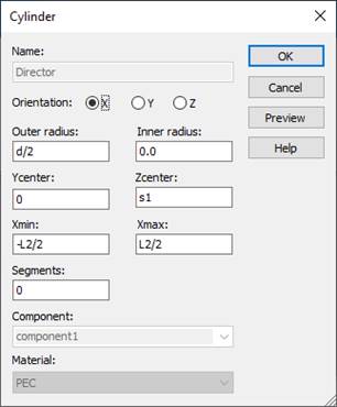
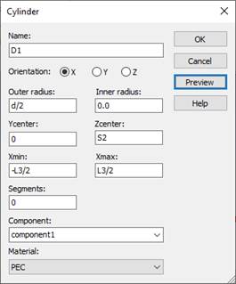
B. Make Director wire using
parameter symbols.
Modeling, Cylinder icon, ESC key, Name: solid1,
Orientation: x
Outer radius: d/2, Inner radius: 0
Y center:0 Z center:s1
X min:
-L2/2 X max : L2/2
Material : PEC
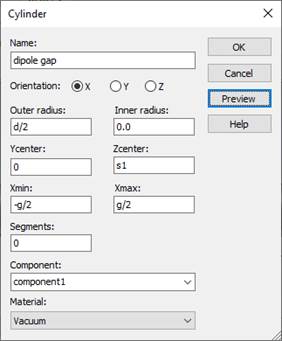
C. Make a feed gap
Modeling, Cylinder icon, ESC key, Name: solid1,
Orientation: x
Outer radius: d/2, Inner radius: 0
Y center:0 Z center:0
X min:
-g/2 X max : g/2
Material : Vacuum
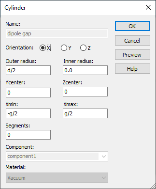

Shape intersection: Cut away highlighted shape
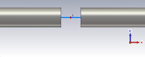
(3) Add an antenna source. Set up a discrete port.
Specify the surfaces between
which a discrete port is to be applied.
Modeling
Picks, Pick Points, Pick Face Center
Place the mouse point on the one of gap faces and then double click.
(4) Simulate
Simulation, Setup Solver, Start
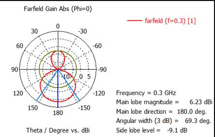
2) Plot the Dabs polar pattern on the E plane(zx-plane). Scale: max. 10dB, min. –15dB.
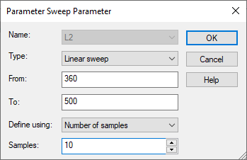
Change the
director length from 0.36 wavelength to 0.50 wavelength in 10 steps.
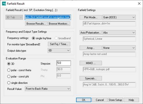
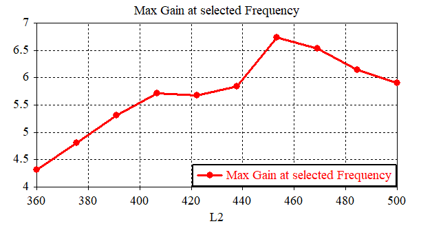
3) Plot the maximum directivity(dB) versus
the director length.
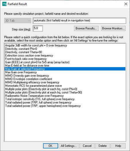
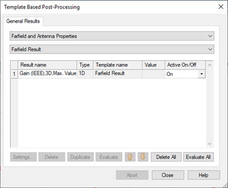
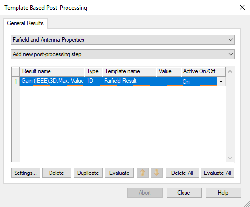
Post-Processing,
Result Templates Tools
General
Result
-
Farfield and Antenna Properties
-
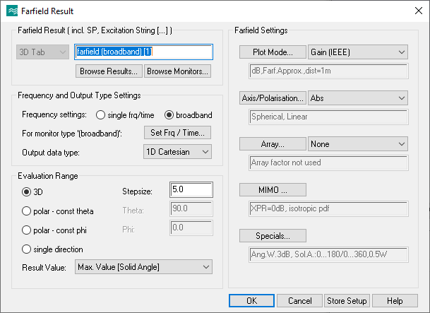
Farfield Result
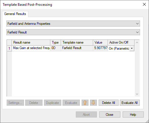
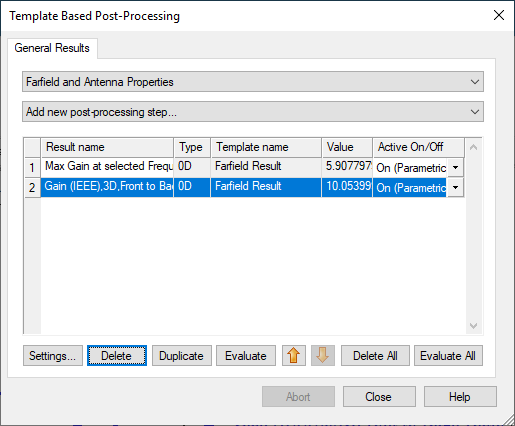
Max gain at
selected frequency
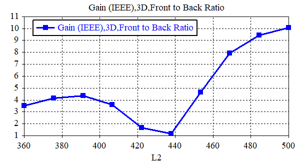
Max gain at
selected frequency, Front-to-back ratio
Home,
Parameter Sweep
New
Sequence1, New Parameter Sweep
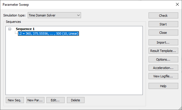
Start
Navigation
Tree, Tables, 0D results
4) Plot the front-to-back ratio(dB).
For the director length of 0.48 wavelength:
5) Plot the Dabs polar pattern on the E plane(zx-plane). Scale: max. 10dB, min. –15dB.
2. Three-element
Yagi antenna
Frequency:
300MHz(wavelength 1m)
Feed gap: 0.01
wavelength
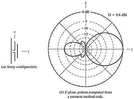
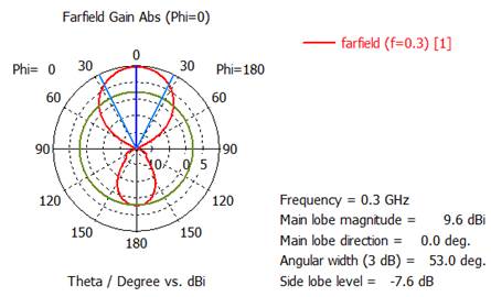
그림: 반사기+급전기+지향기 구조의 방사패턴. 급전기 길이 0.47λ, 반사기 길이 0.48λ, 지향기 길이 0.44λ 도선간 간격 0.20λ, 도선 직경 0.01λ
For the reflector length of 0.48 wavelength:
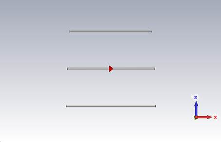
1) Plot the antenna geometry.
Write the
parameter
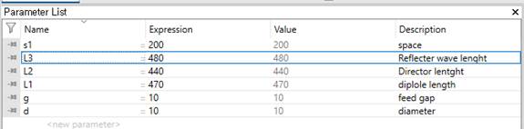
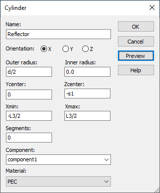
Make Reflector wire using parameter symbols.
Modeling, Cylinder icon, ESC key, Name: solid1, Orientation: x
Outer radius: d/2, Inner radius: 0
Y center:0 Z center:-s1
X min: -L3/2 X max : L3/2
Material : PEC
Simulate
Simulation, Setup Solver, Start
2) Plot the Dabs polar pattern on the E plane(zx-plane). Scale: max. 10dB, min. –15dB.
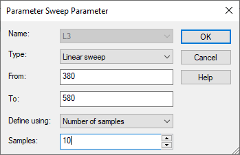
Change the reflector from 0.38 to 0.58
wavelength in 10 steps.
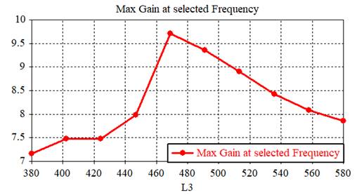
3) Plot the maximum directivity(dB) versus
the director length. Scale: max. 10dB, min. –15dB.
Home,
Parameter Sweep
New Sequence1

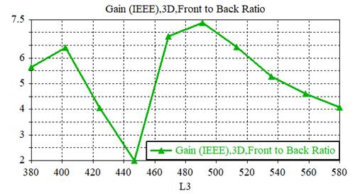
4) Plot the front-to-back ratio(dB).
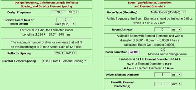
3. 11-Element
Yagi Antenna
ㅇ 안테나 치수 결정
- K7MEM 야기 안테나 설계 프로그램에 접속하여 아래와 같이 설정
K7MEM
Yagi Antenna Design: http://www.k7mem.com/Ant_Yagi_VHF_Quick.html
- 주파수: 700MHz
- 이득: 12dBd = 12
+ 2.15 = 14.15dBi
- Reflector
spacing: 0.20 wavelength(DL6WU)
- Director
element spacing: DL6WU spacing
- Boom type:
Non-metallic boom
- Boom
diameter: 0mm
- Driven
element diameter: 8mm
- Parasitic
element diameter: 8mm
-
Design/Example Viewing: Metric
위와 같이 설정 후 [View
The Design] 클릭하여 다음 그림과 같은 결과를 얻는다.
Boom은 비금속 직경 0mm로 하였기 때문에 존재하지 않는다 (그림에는 있지만).
1) 700MHz
12dBd 야기 안테나 설계결과 제시
급전 다이폴 길이 대 파장: 200.6/428.6
= 0.467
급전 다이폴 길이대 직경비: 200.6/8 =
25
ㅇ 설계한 야기 안테나 특성해석: CST
Studio 사용
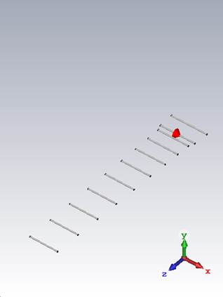
- 좌표축: 야기 안테나 축 = z 축, 도선 축 = x 축과 평향
- 도선을 PEC 원통(내부가 꽉 찬)으로 하여 위에서 설계한 야기 안테나의 형상 생성
- 급전기 중간 급전용 간격: 8mm 제거(도선 직경과 동일)
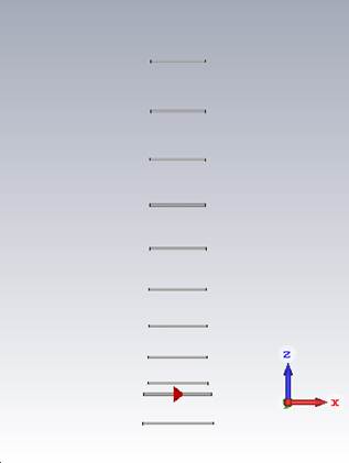
2) 700MHz 12dBd 야기 안테나 형상 제시
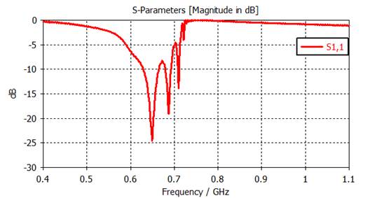
3) |S11|(dB) 반사계수 도시:
400-1100MHz, -30dB to 0dB
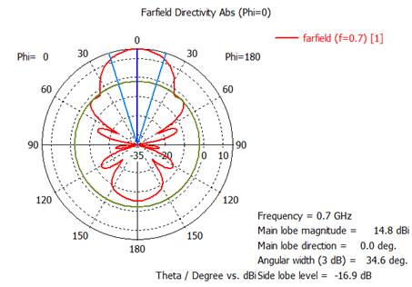
4) 700MHz에서 Dabs 전계면 polar 패턴 그래프 제시: phi =
0º, theta = 변수, -35dB to
15dB
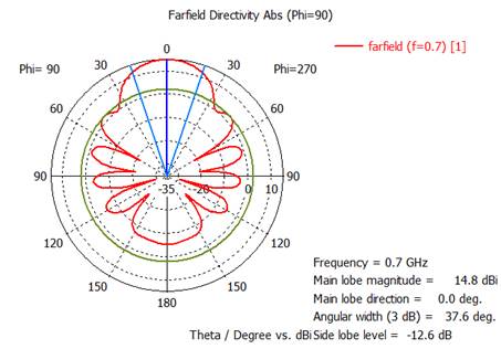
5) 700MHz에서 Dabs 자계면 polar 패턴 그래프 제시: phi =
0º, theta = 변수, -35dB to
15dB
6) 700MHz에서 설계한 야기 특성분석
최대이득 = ( )dBi
전계면 빔폭 = ( )°
자계면 빔폭 = ( )°
전후방비 = ( )dB
7) 주파수에 따른 최대이득 도시: 400-1000MHz범위에서 50MHz 간격으로, 수직축 0-20dBi 범위
1) 700MHz
12dBd 야기 안테나 설계결과 제시
K7MEM Yagi Design Page 접속, http://www.k7mem.com/Ant_Yagi_VHF_Quick.html
단위 수정, 수치 입력
소자 위치와 소자길이 표시됨.
결과 도시
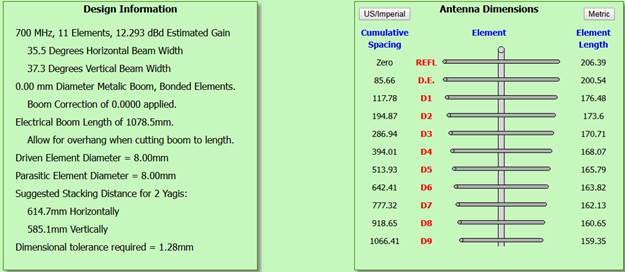
2) 700MHz 12dBd 야기 안테나 형상 제시
(1) Make a
project template.
New Template, Microwaves & RF /
Optical, Anennas
Create Project Template: Wire, Time Domain
Units: default (mm, GHz)
Frequency Min. : 0.4GHz
Frequency Max. : 1.1GHz
Monitors: E-field, H-field, Farfield
Defined at: 0.7GHz
Template name: Yagi antenna
(2) Make a dipole antenna structure.
Write the parameter
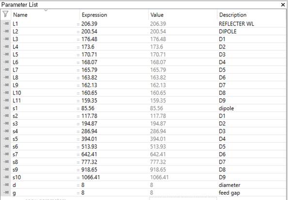
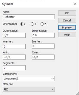
A. Make Reflector wire using
parameter symbols.
Modeling, Cylinder icon, ESC key, Name: solid1,
Orientation: x
Outer radius: d/2, Inner radius: 0
Y center:0 Z center:0
X min:
-L1/2 X max : L1/2
Material : PEC
B. Make Dipole wire using
parameter symbols.
Modeling, Cylinder icon, ESC key, Name: solid1,
Orientation: x
Outer radius: d/2, Inner radius: 0
Y center:0 Z center:s1
X min:
-L2/2 X max : L2/2
Material : PEC
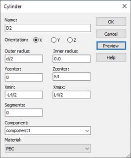
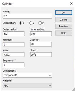
C. Make D1-D9 (Directors) wire
using parameter symbols.


D. Make a feed gap
Modeling, Cylinder icon, ESC key, Name: solid1,
Orientation: x
Outer radius: d/2, Inner radius: 0
Y center:0 Z center:s1
X min:
-g/2 X max : g/2
Material : Vacuum
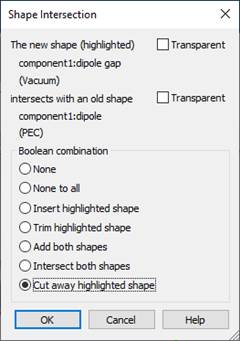
Shape intersection: Cut away highlighted shape
(3) Add an antenna source. Set up a discrete port.
A. Specify the surfaces between
which a discrete port is to be applied.
Modeling
Picks, Pick Points, Pick Face Center
Place the
mouse point on the one of gap faces and then double click.
(4) Simulate
Simulation, Setup Solver, Start
3)
|S11|(dB) 반사계수 도시:
400-1100MHz, -30dB to 0dB.
4) 700MHz에서 Dabs 전계면 polar 패턴 그래프 제시: phi =
0º, theta = 변수, -35dB to
15dB
5) 700MHz에서 Dabs 자계면 polar 패턴 그래프 제시: phi =
0º, theta = 변수, -35dB to
15dB
6) 700MHz에서 설계한 야기 특성분석
최대이득 = ( 14.8 )dBi
전계면 빔폭 = ( 34.6 )°
자계면 빔폭 = ( 37.6 )°
전후방비: 14.8 - (-5) = 19.8dB
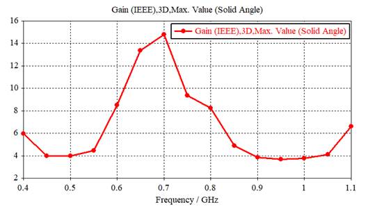
7) 주파수에 따른 최대이득 도시: 400-1000MHz범위에서 50MHz 간격으로, 수직축 0-20dBi 범위
Field
Monitors, double click the farfield (f=0.7)
Check the
Transient Broadband
Samples: 15
with (50MHz)
Make a
farfield (broadband)

Apply, Ok
Simulate
Simulation, Setup Solver, Start
Post-Processing,
Result Templates,
Ok
Evaluate