안테나설계 실습보고서
실습-05 Corner Reflector Antenna
II. Problems
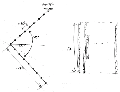
1. Draw a cross-sectional diagram of a
wire-grid corner reflector antenna with the following dimensions
![]() (2a: grid wire's
diameter)
(2a: grid wire's
diameter)
(Solution)
2. Find the wire transmission coefficient in Problem 1.
(Solution)
From the Mumford nomograph with
grid spacing of 0.25 wavelength and the ratio 10 of grid spacing to wire
diameter, we obtain
|S21|(dB) = 10log(1-|Γ|2)= -11dB
3. Find the wire grid efficiency (for gain) in Problem 1.
(Solution)
![]()
4. Describe the design philosophy for each of the following parameters.
a) Corner angle
(Solution) A practical corner angle ranges from 60 to 90
degrees.
b) Apex to dipole distance
(Solution) The apex-to-dipole distance depends on the corner
angle. We adjust the dipole length and the apex-to-dipole distance for good
impedance matching. For 90-degree corner angle, the apex-to-dipole distance
ranges from 0.25 to 0.50 wavelength.
c) Corner reflector length
(Solution) The corner reflector length has an effect on the
antenna gain and the front-to-back ratio, both of which increase with the
corner reflector length. Its minimum value is twice the apex-to-dipole
distance. Its practical maximum value is two wavelengths.
d) Corner reflector height
(Solution) The antenna's gain and the front-to-back ratio
depend less sensitively on the corner reflector height than on the corner
reflector length. Suitable value ranges from 0.75 to 1.5 wavelengths.
e) Wire diameter in the wire grid reflector
(Solution) With the grid spacing fixed. the larger the wire
diameter, the smaller the back radiation. The practical value of the wire
diameter is determined considering the mechanical strength and the antenna
weight. Suitable value is about 1/20 of the wire length.
f) Spacing between wires in the wire grid reflector
(Solution) The grid spacing determines the back radiation
and thus the forward gain. The smaller the spacing, the less the back
radiation. Suitable value ranges from 0.1 to 0.2 wavelength.
g) Broadening the bandwidth
(Solution) To increase the bandwidth of a corner reflector
antenna, the dipole is modified into a thick dipole, a bowtie dipole, a fan
dipole and a butterfly dipole.
III. Lab
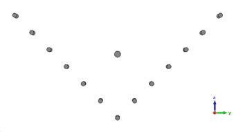
1. Design
![]()
Dipole-to-apex distance = 0.44λ = 189mm
Wire grid: wire length = 0.6λ = 257mm
Wire spacing = λ/6 = 71.5mm
Number of wires in the grid reflector = 13
Wire length-to-diameter ratio = 20 → Wire
diameter = 1.30mm
Dipole length = 0.32λ = 137mm
Dipole length-to-diameter ratio = 8 →
Dipole diameter = 17mm
Dipole gap = same as the diameter = 17mm
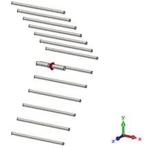
2. Simulate
a) Antenna model generation
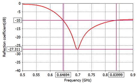
b) |S11|(dB)
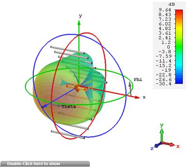
c) Gabs pattern: 3D
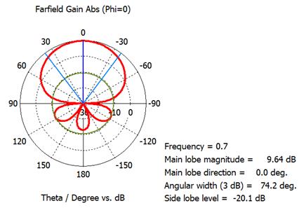
d) Gabs pattern: polar pattern at phi = 0º
(E-plane)
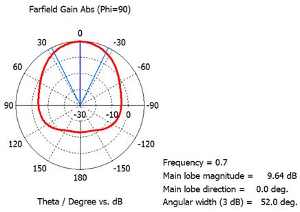
e) Gabs pattern: polar pattern at phi =
90º (H-plane)
3. Analyze the results.
a) Find the antenna bandwidth for |S11| < -10dB in MHz.
Δf = 834-647
= 187MHz
b) Find the maximum gain Gmax(dB).
Gmax = 9.64dB
c) Find the E-plane beamwidth BW-E(deg).
BW-E = 74.2º
d) Find the H-plane beamwidth BW-H(deg).
BW-H = 52.0º
e) Find the front-to-back ratio F/B(dB) over
180º±30º
F/B = 9.64-(-12) = 21.6dB