Lab-07-Microstrip
T-junction Power Divider
1. Theory
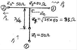
1) T-junction Design
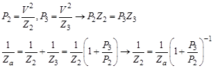
2) Input Quarter-wave Transformer Design
![]()
![]()
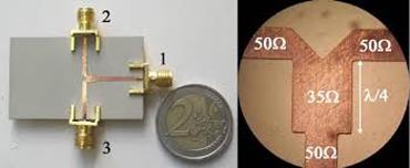
3) A 50-ohm Based T-junction Power Divider Design
2. Application
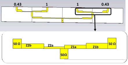
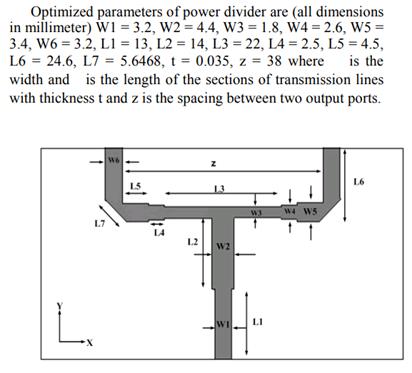
1) Non-equal ratio power divider: Zulkifli(13-IEEE)
2) Octave-bandwidth power divider: Tiwari(18-IEEE)
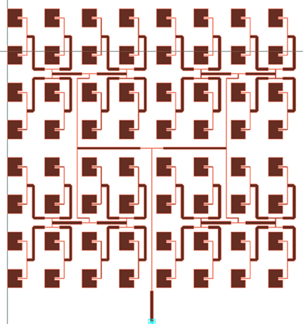
3) A parallel feed network for a
8x8 patch array
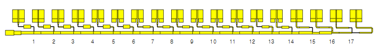
4) A series feed network for a 17-element linear
array of patches
3. Laboratory
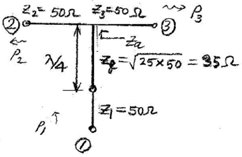
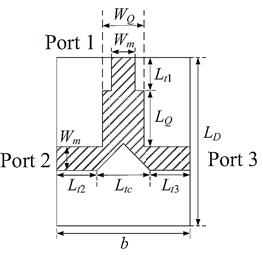
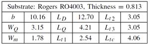
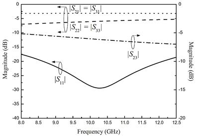
Figure: A design of a microstrip T-junction power divider [Chuang, 2014,IEEE]
Rogers RO4003C: datasheet
��r
= 3.55, h = 0.813mm, tan�� = 0.0027 @
10GHz, t = 0.034 mm for 1oz. copper)
Microstrip
calculaltion: Use http://mcalc.sourceforge.net/
f = 10 GHz
w = 1.78 mm for Z0 = 50 ��
Effective
dielectric constant = 2.8452
Conductor
roughness = 0
Loss
= 5.23 dB/m = 1.49 dB/m (due to conductor) + 3.74 dB/m (dielectric loss)
Conductor
loss with 10-um roughness = 2.97 dB/m
1) Make the geometry.
2) Simulate the scattering
parameters.
3) Plot the magnitudes of S11, S21
over 7-14 GHz.
4) Find the frequency range for
|S11| < -20 dB.