ICT083 Antenna Design
Linear Array Antennas, Basic Level
I. Theory
1. Introduction
1) Why use array antenns?
- Narrow beam or high
gain antenna
- Electronic beam scanning:
Phased array antenna
- Smart antenna: Adptive
digital beamforming
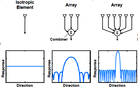
Figure: Antenna arrays and
their directivity patterns [O'Donnell]
2) Linear array:
- Place many antenna
elements on a straight line (= array axis).
- Narrow beam in the
plane of the array axis.
- Wide beam in the
orthogonal plane
3) Applications of linear array antennas
- Mobile communication base
station antennas
- Marine navigational radar
antennas
- Broadcast transmitting
antennas
- Radio astronomy antennas
4) Constituents of an antenna array
- Array elements: Radiators,
radiating elements
- Feed network: Series,
parallel, series/parallel, space-fed
- Array beam control unit:
Passive, active
2. Theory of Antenna Arrays
2.1 Two-element array

Figure: Two-element array of
an ideal dipole
An ideal dipole with z-directed current at origin:
![]()
![]()
Two-element array of an ideal
dipole:
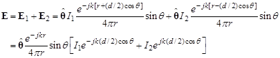
![]() (element factor)
(element factor)
![]() (array factor)
(array factor)
![]() (pattern factor)
: principle of pattern multiplicaton
(pattern factor)
: principle of pattern multiplicaton
EF(element factor): Radiation pattern of a
single element of the array
AF(array factor): Radiation pattern due to
the element arrangement
PF(pattern factor): Radiation pattern of an
array antenna
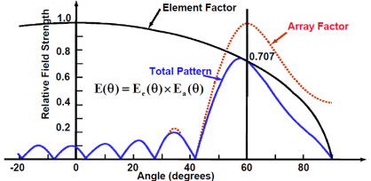
Figure: Principle of pattern multiplication
[O'Donnell]
Simple examples of array factor:
- Element: Isotropic radiator
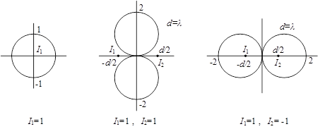
Figure: Simple
examples of array factor
2.2
Linear Arrays
2.1
Array factor of a linear array

Figure: Uniformly spaced
linear array [Stutzman]
![]() : element position
: element position
![]() : element current
: element current
An : current magnitude
nα : current phase
![]()
![]()
Beam scanning:
![]()
![]() : phase difference between elements
: phase difference between elements
(Important) The main lobe is tilted in the
direction of decreasing phase.
![]() : Scan to the left
: Scan to the left
![]() : Scan to the right
: Scan to the right
The
case ![]() is symmetric to
the case
is symmetric to
the case ![]() .
.
Broadside, scanned and endfire array:
- Broadside array: ![]()
- Endfire array: ![]() or
or ![]()
- Scanned array: ![]()


Figure: Broadside, endfire, and scanned arrays
[Balanis]
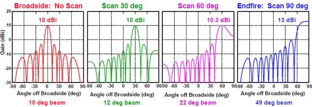
Figure: Broadside, scanned, and endfire arrays
(N = 20, d = λ/4) [O'Donnell]
2.2 Graphical Methods of Array Pattern Plotting
Uniformly excited linear arrays:
![]()
![]()
![]() : normalized
array factor
: normalized
array factor
Properties of ![]() :
:
-
Maximum at ψ = 2nπ (n = 0, ±1, ±2, ...)
-
Period of ψ : 2π
-
Symmetric with respect to ψ = π
-
Distance between nulls:
![]() : major lobes
: major lobes
![]() : minor lobes
: minor lobes

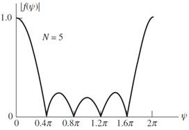
Figure: Array factor of uniformly excited
linear arrays with N = 3 and 5
[Stutzman]
Graphical Methods for Plotting the Array Factor:
- First plot the array factor ![]()
- Next plot a circle for the polar radiation
pattern diagram with radius ![]() and center at
and center at ![]() .
.
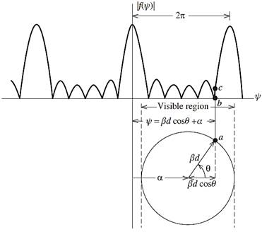
Figure: Graphical method for plotting a polar
pattern of the array factor [Stutzman]
Uniform
two-element array:
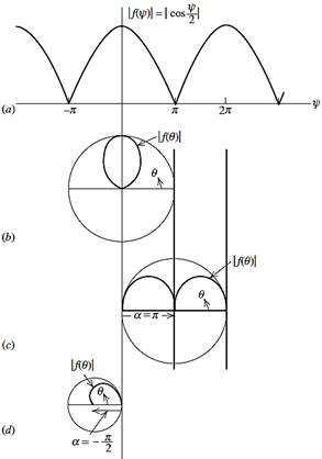
Figure: Pattern plot for uniform two-element
array. (b) d = 0.5λ, α = 0, (c) d = 0.5λ, α = π, (d) d = 0.25λ, α = –π/2
Four-element
scanned array:
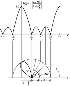
Figure: Examplex of array factor plotting (N = 4, α = π/2, d = λ/2)
[Stutzman]
2.3 Grating Lobes
- Grating lobe: More than one major lobe
![]()
![]()
AF is maximum when
![]()
![]() : Main lobe
: Main lobe
![]() : Grating lobes
: Grating lobes
No grating lobe condition:
![]() : Visible region
: Visible region
![]()
![]()
![]()
![]()
![]()
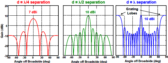

Figure: Grating lobes in 10-element broadside
(top) and enfire (bottom) arrays with element spacing of λ/4, λ/2, and λ [O'Donnell]
II. Exersice Problems
Element:
Half-wave dipole
Element
spacing: d
Dipole
current: In y direction
Array
current distribution: Magnitude = uniform with phasing to be designed for beam
scanning
Array
axis: In z direction
Design
the following array plot the element factor, the array factor, and the pattern
factor in the E- and H-plane.
No
part of the grating lobe appears in the visible region.
1. N = 2, ![]()
2. N = 5, ![]()
3. N = 6, ![]()
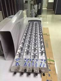
III. Examples of Linear Array Antennas
![[IMG]](array-antenna-theory.files/image120.jpg)
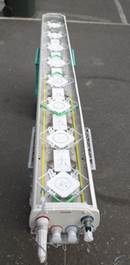
Figure: Linear array antennas in mobile
communicatios base stations [ESTEL, Wirelesse Adviser.com, PPG Cuming
Microwave]

Figure: Linear array of circularly polarized
antennas for terrestrial TV broadcast transmission at 50-200MHz (Channels 2 to
6) [Alan Dick]
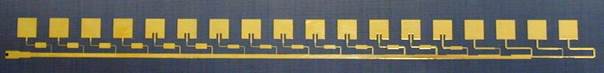
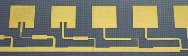
Figure: Linear array of patches. 16.25GHz 18
elements, 0.48λ spacing, 35°
scan