Antenna Design, Monopole
Antenna
I. Theory
1. Monopole Structure

Figure:
A monopole antenna (left) versus a dipole antenna (right)
-
Lower half arm of the dipole is replaced with a perfect electric conductor (PEC).
-
It is also called an antenna ground
plane.
-
A device case or platform often
serves as an antenna ground plane.

Figure:
A device case or chassis can be used as an antenna ground plane.
-
Resonant length (for Xin = 0) can be obtained from the dipole result.
Table:
Dipole resonant length versus wire diameter [Stutzman]
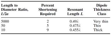
Example:
Monopole length = 100 mm, monopole diameter = 3 mm
Dipole
length = 200 mm, L/2a = 200/3 = 67
2. Image Theory

Figure:
Image principles.
-
Find the field due to a current radiating above an infinite PEC ground plane
-
Remove the PEC ground plane.
-
Place an image current.
-
The field above the ground plane is a
sum of the fields due to the current and its image.
-
The field below the ground plane is zero.
3. Monopole Impedance and
Radiation Pattern
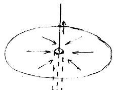
Figure:
Current on a monopole fed by a coaxial cable.
-
The current on the ground plane flows in
the radial direction.

Figure:
Voltage and current on a dipole (left) and a monopole (right)
-
Input impedance of a monopole is one half of the dipole input impedance.
![]()
![]()
-
Resonant monopole
Resonant
length = 0.22 wavelength (thick monopole) to 0.24 wavelength (thin monopole)
Resonant
resistance = 35 ohms (thin monopole) to 20 ohms (thick monopole)
Resonant
reactance = 0 ohm
-
Directivity of a monopole on an infinite ground plane is twice that of a
dipole.
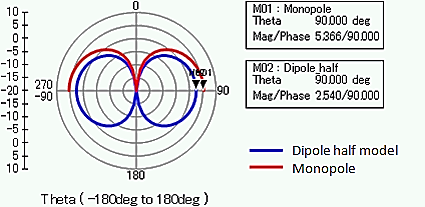
Figure:
Directivity patterns of a dipole (blue) and a monopole on an infinite ground
plane (red)
![]()
![]()
![]()
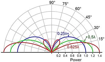
Figure:
Relative directivity patterns of a monopole on an infinite ground plane

Figure:
Normalized directivity patterns of a quarter-wave monopole on a circular ground
plane of radius a. (a) a = 1λ, (b) a = 2λ, (c) a = 6λ,
(d) a = 10λ, (e) a = 20λ. From Z. Zivkovic et al.,
"Radition pattern and impedance of a quarter wavelength monopole antenna
above a finite ground plane", Proc. IEEE 20th Int. Conf. Software,
Telecomm. Comp. Networks, 2012, pp. 1-5.
- Even with a large
ground plane, it is difficult to completely block the field in the lower
hemisphere.
- In the above figure, with a 40-λ diameter ground plane, the field behind the ground plane is
reduced by only 9 dB.
4. Various Forms of The
Monopole Antenna
4.1 Sleeve Monopole
- Enclose the base of the monopole with a conducting
cylinder.
- Banwidth is greatly increased.

Figure: Sleeve monopole structure. From W. L. Week, Anenna
Engineering, McGraw-Hill, 1968.
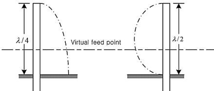
Figure: Principles of the bandwidth extension in the sleeve
monopole
- Sleeve can be of open type.

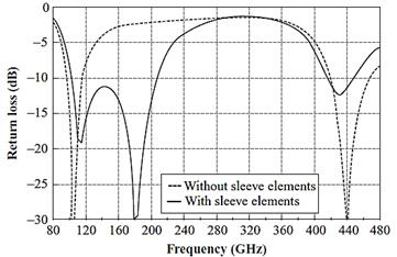
Figure: A cross-T-wire top-loaded open-sleeve monpole.
Dimensions (in λ): driven
element 0.13, top-loading element 0.035, sleeve 0.09-0.11 (tuning), driven
element to sleeve 0.049, wire radius 0.0075. From L. J. Ying and G. Y. Beng,
"Characteristics of broadband top-loaded open-sleeve monople", IEEE
AP-S Int. Symp. Dig., 2006, pp. 635-638
4.2 Monpole
with Radials
- Groun plane is realized usign quarter-wave radials.

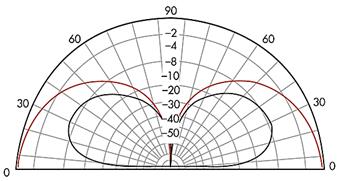
Figure: A monopole with radials (left) and its directivity
pattern (right).
From www.kingscountyradioclub.com
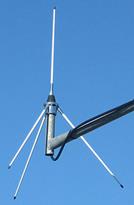
Figure:
A VHF monopole with three radial wires. From Wikipedia.
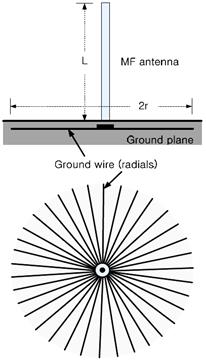
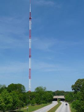
Figure:
A MF broadcast monopole antenna with radials buried in the earth. 0.53-1.6 MHz,
50-1500 kW. From Wikipedia.


Figure: An array of sleeve monopoles for the TCI 802 DF
system operationg at 0.3-30 MHz. From www.tcibr.com
4.3 Shortened Monopoles
- Monopole length reduction methods
Base
inductive loading
Middle
inductive loading
Top
capacitive loading
Top
capactive and inductive loading
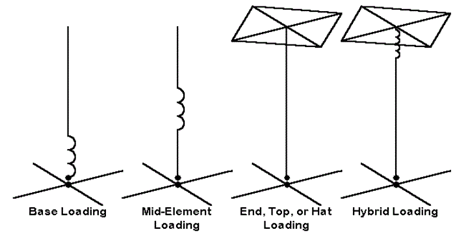
Figure: Monopole length reduction techiques. From webclass.org/k5ijb/antennas/Vertical-antennas.htm.
- Top-loaded monopole antenna

Figure: Top-loaded monopole
antennas of VLF and LF applications. From J. L.
Volakis, Antenna Engineering Handbook, 4th Edition, McGraw-Hill, 2007.
- Whip antenna: Use a wire of helical shape for size reduction
- Also known as (aka) a normal mode helical antenna or a
helical monopole antenna.
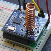
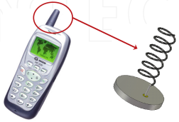
Figure: Whip antennas for (a) 315/433 MHz short range radio [www.embien.com] and (b) 46/49 MHz wireless telephone [L. Huiteman, Progress in Compact Antennas, Chapter 1 Compact
Antennas – An Overview]
4.4 Compact Monopole Antennas
1) Meander
monopole

Figure:
Meander monopole in a USB Bluetooth dongle. From www.qsl.net/kk4obi/
2) ILA (Inverted L Antenna)
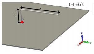
Figure: Inverted L antenna (ILA) [L. Huiteman,
Progress in Compact Antennas, Chapter 1 Compact Antennas – An Overview]
3) IFA
(Inverted F Antenna)
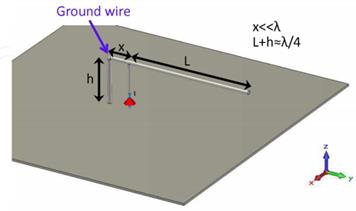
Figure: Inverted F antenna (IFA) [L. Huiteman,
Progress in Compact Antennas, Chapter 1 Compact Antennas – An Overview]
-
Printed IFA
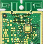
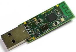
Figure:
Printed inverted F antenna. MIMO antenna (left) and
(b) USB dongle Bluetooth antenna
4.5 Planar Monopole
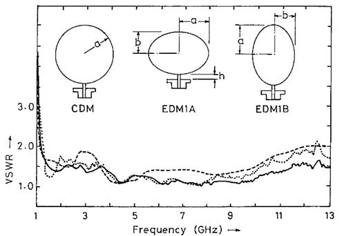
Figure:
Planar monopole antenna. From N. P. Agrawall et al.,
"Wide-band planar antennas", IEEE Trans. Antennas Propagat.,
46(2), 294-295, 1998.
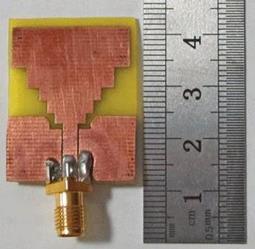
Figure:
A wideband plate monopole.
4.6 3D Monopole
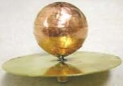


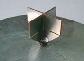
Figure: Various 3D monopole shapes
4.7 Low-profile Monoples

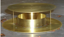
Figure: A low-profile monopole design example. 0.5-2.7GHz, D = 123 mm, H = 43 mm [After Ravipati]