Capacitors for Power
Electronics
[Ref
Abdi(15) electrolytic,
smps's failure rate
#Avnet(an) power
converter dc-link cap selection
Bilgin(19) dc-link cap
lifetime
Buiatti(11) power
converter cap online monitoring
Chidley(17) ESR in
electrolytic cap
#Cornell-Dubilier(-) al
electrolytic appl guide
Dang(20) electrolytic, health
monitoring
Flicker(12) pv
inverter, bus cap role
Flicker(13) film cap,
lifetime test
Flicker(15) pv inverter
cap reliability
Flicker(15-TR) pv
inverter cap reliability
Gupta(19) cap
degradation modeling
Hacke(20) pv inverter
dc-link cap evaluation
Kemet(15,ppt)
capacitors
Kynix(18) solid cap
Moon(16) dc-link cap
estimation
NIC Components(ppt) low
esr cap for high current app
Nguyen(15) ESR estimation
Nichicon(cat) cap power
supply lighting
Nippon
Chemi-Con(09,ppt) conduc poly al solid cap, AN
Passive-components-eu(an)
dc-dc converter output capacitance calc
Peterson(20) power
supply filtering cap selection
Prymak(98) tantalum
capacitors power supply
PSMA(18,ppt) how to
select power supply cap
#Rachev(20) dc-link cap
selection
Salcone(09) dc-link film
cap selection
Shimbun(13) conductive
polymer, aluminum solid electrolyte, PZ-CAP, power supply
#Sponar(-) dc-dc converter
output cap benchmark
Sun(20) flying cap design
#Tech Web(an) input cap
selection
#Tech Web(an) output cap
selection
TI(slta055) in out cap
selection
TI(slva157) induc cap dc-dc
conv
#TI(ppt) cap selection
dc-dc converters
TKD guide to replacing
electrolytic with MLCC
Vishay low ESR tantalum
capacitors
#Vishay(-) power supply al
cap
Zhao(13) electrolytic cap
stress analysis
[Products
1. CBB137
100uF 100V 4mohm,
metalized polypropylene film cap, 최소
700개,
개당7불
2. 250V 47uF 오디오
무전극,
$19.51
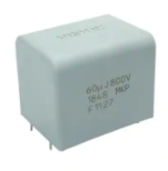
3. 800V 10uF,
DC-Link, PP film, $5.56,
3b. 800V, 40uF, dc-link, $11.14,
10개
https://ko.aliexpress.com/item/4000318008752.html
4. 400V 200UF 36,000원, 최소주문 56개
https://kr.mouser.com/ProductDetail/WIMA/DCP4G062007KD4MSSD?qs=RB4whv9F6rw68Rexa3vOBg%3D%3D
5. Wima, 100uV, 500V, 35*50*42* 1.9mohm, 2.9만원, DCP4H161007J, Wima; 재고 24개
6. Panasonic, 100uF, 500V, 35*56*56, 4.7mohm, 2.4만원
https://kr.element14.com/search?st=film%20capacitor%20100uf
7. TDK, 450V, 200uF, P50*95, 4mohm, 1.8만원, 재고 없음
8. TDK, 450V,
260uF, P50*120, 5mohm, B32320I4267K000, 2.1만,
재고없음
9. KEMET, 500V, 100uF, 1.8만, 재고없음
10. KEMET, 100uF, 2만, 재고없음, 0.0002
11. TDK, 100uF, 1.9만
https://kr.element14.com/w/search/prl/results/2?st=film%20capacitor%20100uf
1. 요약
ㅇ 탄탈륨 커패시터 ESR 100uF 20V 45mohm > 너무 높음
ㅇ 전해커패시터: 1kHz 이하에서 사용,
ESM 0.3 ohm으로
높음
ㅇ 300-3kV 전력용 커패시터는 polyester film 커패시터가 주로
사용됨. 정전용량에 비례하여
크기가 커지며 가격도
개당 10-100만원으로 고가임.
ㅇ 세라믹 MLCC 커패시터: TDK 제품이 대표적.
ESR 작음 (1-10 mohm). 내압 작음(25V for 100uF, 100V for 22uF), 바이어스 전압에 따라
C가 0.8-0.5배로 감소
[ESR
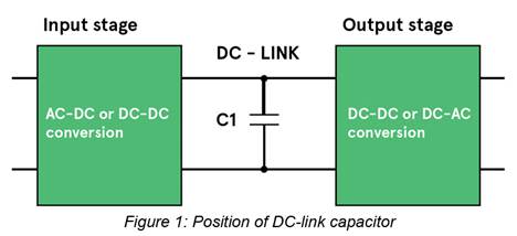
2. DC-Link Capacitors
ㅇ 기능
- Low impedance path
for high-frequency switching currents: output filter for input stage
- Means for energy
storage
- Input stage:
rectifier or PFC circuit
ㅇ 선정
- Capacitance: based on
ripple voltage
- Ripple current:
heating
- ESR: heating
- Operating conditions:
voltage, temperature, power output, line frequency, switching frequency,
lifetime
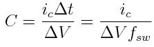
1) Capacitance
- Low power AC-DC w/o
PFC: allowed mains (DC mains) ripple voltage, 2uF/W
- High power AC-DC with
PFC: hold-up or ride-through time on input power loss. Capacitor terminal
voltage is high. Less than 1uF/W.
th*Pc/eta = 0.5*C*V1^2
- 0.5*C*V2^2
th*Pc/eta : energy required
by the load during hold-up. th = hold-up time, Pc=output power, eta =
efficiency
right-hand side:
capacitor's discharged energy
For AC output inverters, hold-up may not be an issue and a minimum capacitance is just needed to be low enough impedance at the inverter switching frequency to minimise voltage ripple.
In practical circuits, the ripple current
that the capacitor must handle without overheating by dissipation in the ESR is
often the overriding factor.
The current can be so high that for a
given voltage, a minimum physical size of capacitor is required to achieve low
ESR, high dissipation and long lifetime.
This often leads to a capacitance which is
well over the minimum from line ripple or hold-up calculations.
The ripple current waveform is very
difficult to predict as it is a combination of line frequency and input and
output stage frequencies and their harmonics.
The wave shapes depend on the topologies
of the stages and can vary from triangular, high-rms currents in discontinuous
mode PFC stages to more square-shaped currents from following bridge converter
or inverter stages.
The input and output stage currents are
sunk and sourced respectively from the capacitor and are not necessarily in phase
or at fixed frequency, complicating matters further. There are schemes however
where the input and output stages can be synchronised to achieve some ripple
current cancellation in the capacitor.
From calculation, experiment or
simulation, headline capacitor specifications can be found but then practical
considerations of size, cost, lifetime and reliability matter.
A designer will see that there are several
types of capacitor which are available for the application, splitting between
aluminium electrolytic, film and ceramic types.
The choice is not easy to make and depends
strongly on the application but the general trade-off is that electrolytics are
cheaper and smaller than film and ceramic types for a given combination of
voltage rating and capacitance (CV ratio) but have lower ripple current rating.
They also have higher variation of
capacitance, ESR and ripple current rating with time and temperature and have a
shorter lifetime, heavily dependent on temperature and applied voltage.
Electrolytics are only available up to
about 600 VDC rating compared with several kV for film types, requiring series
connection of electrolytics with balancing networks in high voltage
applications.
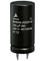
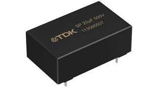
The initial cost of an electrolytic can be
very much less than that of a film type with the equivalent CV ratio. Examples
would be the B43544 series electrolytic (right) and BMKP 3277 series film
types from TDK EPCOS. At 470/480 µF 450V, the film type ESR is about sixty
times lower, the ripple current about nine times higher and the life about four
times longer at similar temperatures and frequencies. However, the electrolytic
is ten times smaller and about one tenth of the cost.
Table 1 gives a summary of the main
specifications of the two examples. Perhaps more important is the way the
specifications of the two types vary with the environment and application
conditions.
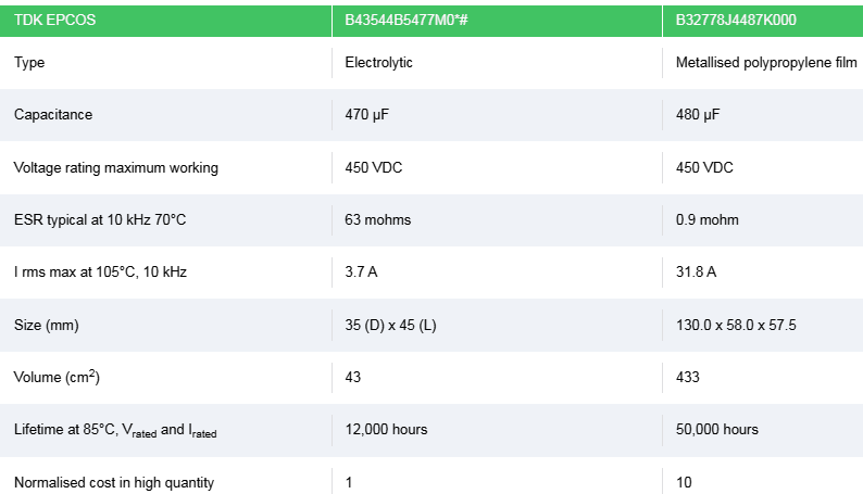
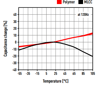
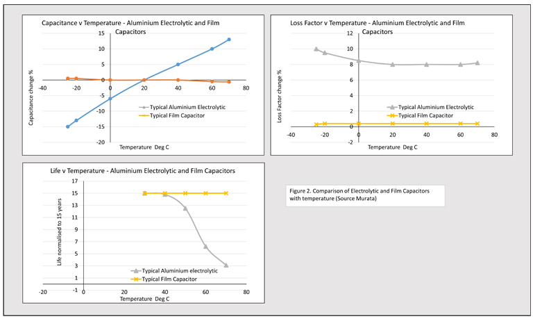
Figure 2 shows how the capacitance, loss
factor and life of typical electrolytic and film capacitors vary with
temperature. End of life of a capacitor is defined as degradation of
performance down to a particular level, typically a variation of capacitance of
greater than 20% from initial value, a dissipation factor change of more than
1.3 times initial value or leakage current greater than initial specified
limit. If this cannot be tolerated and the component is used at high temperature,
it may be necessary to change it out many times during the life of the end
equipment with the associated purchasing, rework and down-time costs.
There is clearly a major difference in
life time between the two types but during the expected life of an electrolytic
capacitor, its inherent reliability is actually not too different to film or
ceramic types. TDK -EPCOS quotes 10 FITS (failures in 109 operating hours) at
0.5 Vrated and 40 ˚C for the example film capacitor and although the company
does not quote a figure for the electrolytic in its data sheet, typical field
failure rates of 0.5 to 20 FITs have been reported for electrolytics in
general. Under voltage stress, film types do have the advantage that they
are to an extent self-healing and can take higher surge voltages than
electrolytics.
Ceramic DC-link capacitors such as the CeraLinkTM
range (left) from TDK EPCOS are only available currently up to capacitances of
about 20 µF at 500 V (part B58033I5206M001) but if 23 were paralleled to
achieve a comparable 460 µF at 192 cm3, they would promise potentially huge
ripple current handling. Each one is rated at 31.5 A at 100 kHz, 85˚C so 23
together would handle a staggering theoretical 724 A. Like with other ceramic
capacitors, however, the capacitance and ESR value does vary strongly with
applied voltage and temperature.
To summarise, the choice of capacitor type
is very dependent on the application, and electrolytics are still a very good
option when cost is sensitive and the environment is not harsh. When
temperatures and ripple currents are high, opting for an electrolytic instead
of film can be a false economy when considering the costs of a shorter life
leading to expensive replacement and down time. TDK EPCOS has a wide choice of
both capacitor types suited for harsh conditions and in various mounting
formats.
Avnet
Abacus has developed a new interactive tool help you navigate TDK’s range of
products for inverters and drives. Use the tool to explore the individual
stages of a drive circuit and identify the most suitable products for your
design. Click here to
go straight to the DC-Link section, where you can access datasheets and
technical information for the products mentioned in this blog and more.
Alternatively, if you have any questions about DC-link circuits, or
you would like to discuss your inverter design in more detail, get in touch with our product specialists.
B58033I5206M001
: 8.5만원 on Mouser
[Ref
efficiency, dc-dc
converter
https://www.maximintegrated.com/en/design/technical-documents/app-notes/4/4266.html
[Capacitor selection
Ceramic
Tantalum
Niobium
Aluminum electolytic
tantalum-polymer, tantalum (MnO 2 with single-
and multi-anode constructions), niobium oxide (MnO2), multilayer
ceramic, and aluminum-electrolytic.
Some 99% of the ‘design’ problems associated with linear and
switching regulators can be traced directly to the improper use of capacitors,”
claims the National Semiconductor IC Power Handbook.
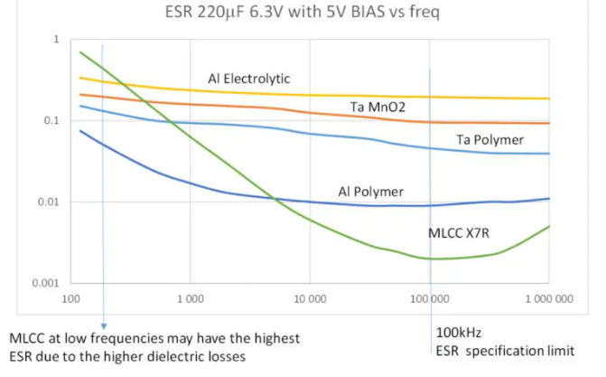
Frequency dependence of capacitance ESR and stability with
operational temperature and dc bias voltage are the important parameters of
output capacitors that define performance and functionality of the complete
power system.
Maxim MAX1537
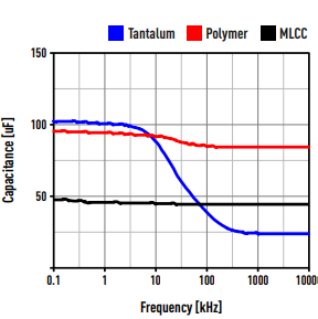
In the case of tantalum-polymer and tantalum-MnO2 multi-anode
capacitors, there is a relatively small drop in capacitance in frequencies from
10 to 100 kHz (Fig. 4), whereas
tantalum-MnO 2 and aluminum-electrolytic capacitors
exhibit a larger drop across the same range. The actual capacitance of the MLCC
capacitor suffers due to its dependence on the dc bias voltage, which was
applied during measurement. Fig. 5 shows
the very low ESR performance of the MLCCs and relatively low ESR of the
tantalum-polymer devices. The ESR of aluminum-electrolytic capacitors is
relatively high over the complete measured frequency range.
Both tantalum single- and multi-anode capacitors retain a
higher capacitance at higher frequencies (above 100 kHz), whereas niobium oxide
and aluminum-electrolytic capacitors lose their capacitance faster at lower
frequencies (Fig. 7). The MLCCs
exhibit very low ESR around the 100-kHz frequency range; tantalum multi-anode
and tantalum-polymer capacitors show low ESR in the same frequency range; and
the aluminum-electrolytic capacitor has a high ESR over all frequency ranges.
1) Article reading
https://www.specterengineering.com/blog/2019/9/7/dc-link-capacitor-selection-for-your-inverter
Film or Electrolytic?
Because, the ripple current ends up
being the driving requirement, most modern inverters use film
capacitors. Compared to electrolytics, film caps have high ripple current
rating due to their low ESR and ESL. Electrolytics have a higher
capacitance/volume ratio than film caps, but the ESR and ESL is much higher so
you need to put many of them in parallel in order to satisfy the ripple current
requirement. The volumetric efficiency typically ends up being much higher if
film capacitors are used. Additionally, the working lifetime rating of
electrolytics is around 10k hours, whereas for film it’s 100k hours [1]. This
is because the electrolyte dries out and leads to increased ESR which increases
power loss and ultimately results in failure.
Ripple
current requirement
Ripple
voltage requirement
ripple current rating: safety factor 1.1
DC voltage rating: maximum bus voltate x 1.1
film cap: x 1.3 for 1 minute
resonant frequency: switching frequency * 2 < resonant
frequency
capacitance rating
- ripple current
- bus voltage
- resonant frequency
- packaging
- cost
* C, ESR (ripple current rating), insulation resistance, voltage
rating: temp. dependent
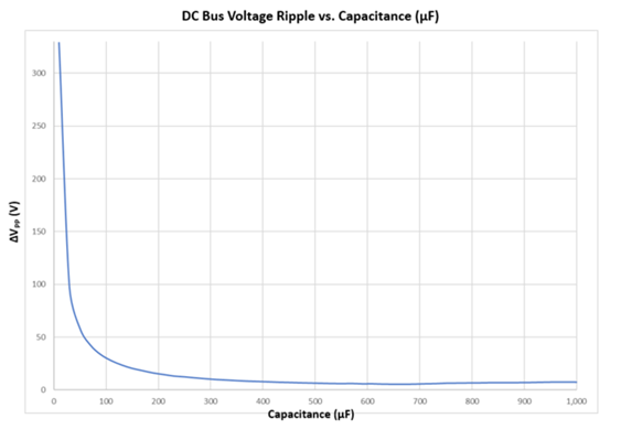
C_min = Iout * duty * (1-duty) *1000/(f * Vppmax)
Vppmax : max ripple voltage
TDK CKG57NX7R1E107M500JJ, 5750*5mm, 100uF, 25V, $11.61, 20kHz
max, 3mohm
디바이스마트 12,980원
디지키 $9.3 up to 50 ea
CKG57NX7S2A226M500JJ, 5750*5 mm thick, 22uF, 100V, $5.4; 100개 사용 220uF, 40kHz max, 10mohm
CKG57NX7S1H226M500JJ, 5750*5mm thick, 22uF, 50V, $4.95
WIMA
DCP4G062007K
300V, 200 uF, 40*55*42, Is = 1600 A, Irms = 32.5A @ 10kHz,
1.2mohm @ 10kHz
https://www.wima.de/en/our-product-range/metallized-capacitors/mks-4/
MKS4D061007H00KSSD, 100UF, 100V, 16,000원
EPCOS/TDK B32320I8207K000,
800V 200uF, 3.6mohm, 1개 가능 24,000원
WIMA, DCP4G062007KD2JSSD, 400V 200uF, 1.2mohm, 1개 가능? 38,000원
Aliexpress
1) Tantalum
https://ko.aliexpress.com/item/1005001510640858.html?spm=a2g0o.productlist.0.0.15e82c0bopkDge&algo_pvid=71d15b48-07c5-431c-bf1a-a0a021e672d4&algo_exp_id=71d15b48-07c5-431c-bf1a-a0a021e672d4-20
35V 33uF
25V 47uF, 100uF
2) Tantalum
35V 100UF,
$2.25
https://ko.aliexpress.com/item/1005002821101179.html?spm=a2g0o.productlist.0.0.15e82c0bopkDge&algo_pvid=71d15b48-07c5-431c-bf1a-a0a021e672d4&algo_exp_id=71d15b48-07c5-431c-bf1a-a0a021e672d4-46
2) MLCC
2220, 100uF,
50V, X5R, 개당 1불
https://ko.aliexpress.com/item/1005002799692129.html?spm=a2g0o.productlist.0.0.15e82c0bopkDge&algo_pvid=71d15b48-07c5-431c-bf1a-a0a021e672d4&algo_exp_id=71d15b48-07c5-431c-bf1a-a0a021e672d4-29
Li-Po battery
Ripple
current reduction
https://www.freepatentsonline.com/y2019/0089171.html
AVX
FTF94F0127*025, 43*45*30; dv/dt = 2V/us, peak current = 240A, SQP=35
Metal
film: size too large
20uF
45*38mm, 8천원
Vishay,
240uF, 800V, film, 57*130, 1.6mohm, 11만원/EA