FSR Literature Study
[Companies
1. PPS, tactile sensor
https://ko.pressureprofile.com/sensors/tactarray
2.
https://www.azosensors.com/article.aspx?ArticleID=1727
3.
https://www.cubbison.com/blog/a-custom-force-sensing-resistor-you-can-trust
4. FSR 응용제품
5. NFC 응용제품
https://ieeexplore.ieee.org/document/9495780/references#references
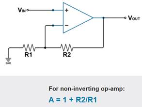
6. Non-inverting amp
7. FSR Tekscan
8. Butler Technologies Inc
Insole pressure sensor
https://butlertechnologies.com/force-sensing-resistor/
9. Sensor Products Inc
https://www.sensorprod.com/tactile-surface-c-sensor.php
10. Interlink FSR integration guide
- Part-to-part repeatability: ±15% to ±25%
- Force measurement repeatability
FSR conductance tolerances
Actuating system repeatability
Measuring system repeatability
- FSR integration consideration
FSR size and shape
Desired mechanical actuation system
Actuation methods: overlays, actuator areas
Electrical interfaces
Force distribution: FSR response = very senstive to
force disribution. Use a thin elastomer to distribute the applied force
Use of adhesive: If force is applied over an area
which includes the adhesive, the resulting response characteristic will be
drastically altered.) In an extreme
case (e.g., a large, flat, hard actuator that bridges the bordering adhesive),
the adhesive can present FSR actuation
Actuation cycle time: FSR mechanical settling time
= on the order of seconds
FSR application type: 1) Force switch = the number
of force threshold in one. 2) Dynamic force measurement = changing force
measurement
Force accuracy calibration: Error spread
measurement
Part calibration: For increased accuracy. Circuit
gain adjustment for each FSR. Or each FSR's resistance is tested and select
only usable units.
Temperature compensation
Spurious results: Due to sensor error or system
error
- Do's and dont's
Avoid air bubbles and any contamination for the FSR
laminating surface.
Use of double-sided laminating adhesives: Cover the
entire surface of the sensor.
Prevent kinks and dents in active areas.
Do not kink or crease the tail of the FSR device if
you are bending it; this can cause breaks in the printed silver traces. The
smallest suggested bend radius for the tails of evaluation parts is about 0.1”
[2.5 mm]. In custom sensor designs,
tails have been made that bend over radii of 0.03” (0.8 mm]. Also, be careful if bending the tail
near the active area. This can
cause stress on the active area and may result in pre-loading and false
readings.
Do not block the vent. FSR devices typically have an air vent
that runs from the open active area down the length of the tail and out to the
atmosphere. This vent assures pressure equilibrium with the environment, as
well as allowing even loading and unloading of the device. Blocking this vent could cause FSRs to
respond to any actuation in a non-repeatable manner. Also note, that if the device is to be
used in a pressure chamber, the vented end will need to be kept vented to the
outside of the chamber. This allows
for the measurement of the differential pressure.
Do not exceed 1mA of current per square centimeter
of applied force (actuator area).
This can irreversibly damage the device.
11. Ohmite FSR integration guide
- FSR types: Shunt mode, thru mode

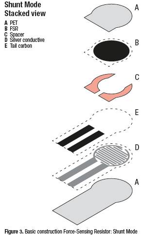
- Shunt mode
Shallower curve giving better control esp. at
higher forces i.e. >100g
Fewer print layers and less silver ink required so
typically cost is < Thru Mode sensors
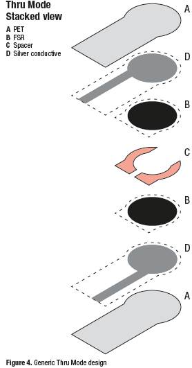
- Thru mode
Force range is limited typically <0.5-1kg
More print layers and more silver ink required so
typically cost is greater then shunt mode
- Interconnection
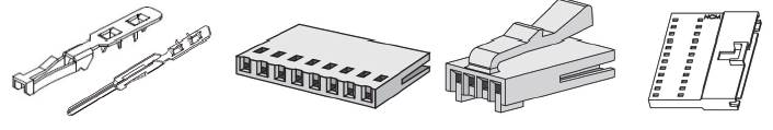
Bare tail
Crimpfl ex series: solder tabs, female and male
connectors
Friction fit: ZIF, TIF, gold / tin / nickel pins
Friction fit with protective overprint
Housing including standard, latch and detent
Other options
- FSR types
Single point: Z axis force only. Square, round, strip. Single senor or
sensor array
Linear potentiometer: Strip or scroll-wheel configuration. X or Y position
with Z-axis force (1D)
3D single-touch: X & Y positions on a single touch
3D multi-touch: Track pad for X & Y positions on multiple touch points