Coaxial Cables
Coax-to-microstrip adapters
End launchers:
Emerson
Network Power: SMA end launch connectors
[Features
of the Coaxial Cable]
- Wide
bandwidth
-
Small size
- Low
power handling capability
- No
dispersion
- High
loss
-
Lines can be bended
-
Imperfect noise shielding
*
Applications of Coaxial Cable
-
Signal routing over a short distance
[Coaxial Cable Structure]

|
Quad-braid |
|
|
|
Triple-braid |
|
|
|
Dual-braid |
|
|
|
Single-braid |
|
|


1) Conductors
AL Tin-plated alumuinum
CU Copper
CW Copper plated steel (Copperweld) =
Copper-clad steel (CCS)
SPC Silver-plated copper
SCW Silver-plated copperweld
SSC Stranded silver-plated copper
TC Tinned copper
-S Strand
2) Dielectrics
|
Acronym |
Full name |
Velocity factor (%) |
εr |
Loss tangent |
|
ASP |
Air space polyethylene |
84-88 |
|
|
|
AST |
Air space Teflon |
85-90 |
|
|
|
FE |
Foam polyethylene |
80.0 |
|
|
|
FEP |
Fluorinated ethylene
polypropylene |
78.6 |
1.62 |
|
|
FS |
Foam polystyrene |
91.0 |
|
|
|
FTPTFE |
Foamed-tape PTFE |
|
|
|
|
FP |
Fluoropolyme, cellular |
84.0 |
1.416 |
|
|
PE |
Polyethylene, solid (PE-S) |
65.9 |
2.30 |
|
|
Polyethylene, semi-solid
(PE-SS) |
82.6 |
1.466 |
|
|
|
Polyethylene, cellular (PS-C) |
83.6 |
1.430 |
|
|
|
PTFE |
Poly-tetra-fluor-ethylene
(Teflon®) |
69.4 |
2.10 |
|
3) Shielding materials (wires and
foils)
Flexfoil
CCS Copper-clad steel
CU Copper
AL Aluminum
TC Tinned copper
[Why 50 Ω for Coaxial Cables?]
In most cases we use Z0 = 50Ω. In TV applications we use Z0 = 50Ω. In an air-filled coaxial cable, Z0 = 75Ω offers minimum
attenuation while Z0 = 35Ω
gives maximum power handling. Z0
= 50Ω is a compromise between these two values.
[Power Handling Capability of a Coaxial
Cable]
- Peak
power handling is limited by the dielectric breakdown.
![]()
- In
the production test, 35% of the theoretical maximum power level is used.
Usually a DC test voltage is applied [1].
-
Average power handling is limited by the temperature rise on the inner
conductor. Typical industry conditions have been to allow the inner conductor
to reach a temperature of 100°C with an ambient temperature of 60°C
![]()
![]() : average power
(W) for 60°C rise of the inner conductor temperature from the ambient
temperature.
: average power
(W) for 60°C rise of the inner conductor temperature from the ambient
temperature.
![]() : heat transfer
coefficient from the inner conductor to the outer conductor and the ambient
environment (W/in2). The following table is from [1].
: heat transfer
coefficient from the inner conductor to the outer conductor and the ambient
environment (W/in2). The following table is from [1].
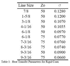
b : radius of the outer
conductor (inch)
![]() : correction
factor for attenuation ralative to 20°C
: correction
factor for attenuation ralative to 20°C
![]()
![]() : temperature
coefficient of the resistance (copper)
: temperature
coefficient of the resistance (copper)
![]() : temperature,
current and reference
: temperature,
current and reference
![]() : attenuation
constant (dB/100ft) at 20°C
: attenuation
constant (dB/100ft) at 20°C
6. Upper Usable Frequency(UUF)
-
Cutoff frequency of the 1st higher-order mode (TE11 mode)
![]()
![]() (usable frequency range)
(usable frequency range)
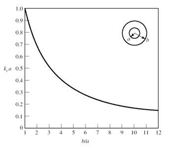
- An
example: RG-142, a = 0.89mm, b = 2.95mm, ![]()
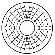
-
Graph of kc (cutoff wavenumber)
7. Attenuation in a Coaxial Cable
-
Conductor loss is proportional to the square root of the frequency, while the
dielectric loss is proportional to the frequency.
![]()
![]()
![]()
-
Attenuation of the real-world cable:
1)
Theoretical attenuation deviates heavily from the measured values because the
theoretical model assumes a conductor of infinite extent (thickness or diameter
in coaxial cable case) in computing the conductor loss.
2)
Attenuation of the real-world coaxial cable is always greater than the
theoretical attenuation of the
ideal coaxial cable due to various
imperfections.
Skin
Effect
- The
resistance and the inductance of both the inner and outer conductors will vary
with frequency because of skin effect. There are no simple general relations
which can be used at all frequencies.
-
Inner conductor: skin effect at low frequencies [Race & Larrick]:
![]()
8. Standard Specifications of Coaxial Cables
-
MIL-HDBK-216 (1962)(obsolete): RG-number, RG-number/U
-
MIL-C-17 (current military standard for coaxial cables): M17/75-RG214
-
RG-series designations are still in use.

[Coaxial Cable Engineering Data]
RG coaxial cable specifications
Antenna feeder cable specifications (LS
Cable)
Coaxial cable calculation by RFS
World
Coaxial cable attenuation table
RF cable selection guide by
Times Microwave Systems
Advanced coaxial
cable capaibilities, Times Microwave Systems
[High-Voltage Cables]
* High-voltage pulse cables:
RG-17A/U (11kV), RG-18A/U (11kV), RG-19A/U (14kV), RG-20A/U (14kV), RG-27A/U
(15kV), RG-28B/U (15kV), RG-36 (13kV), RG-157(15kV), RG-158(15kV),
RG-177(11kV), RG-190(15kV), RG-191/U (15kV), RG-192/U (15kV), RG-193/U (30kV),
RG-194/U (30kV), RG-218(11kV), RG-219(11kV), RG-220(14kV), RG-221(14kV),
RG-230(15kV), RG-328/U (20 kV), RG-329(15kV)
- MIL C-17 specification for HV
coax cable
- Times AA-6778: RG-220 version
with an AL foil tape layer between the poly and the outer braid. This foil
layer helps reduce the air pockets that cause many cable failures. 80kV rating.
[Harris(1991), SLAC-PUB-5489]
- 10kV 10μs rise-time pulse cable design for the modulator in the
superconducting linear accelerator TESLA (120kV 15MW 1.7ms pulse width with PRF
of 5Hz, avg. power 127.5kW): Eckoldt(2000)
* High-peak power cables:
- RG-288 (440kW), RG-321(320kW),
RG-322(320kW), RG-367(830kW)
- HRL875 8-3/16" HRLine
(1800kW)
- HFC42D 1-5/8"
(17.2mm/42.5mm foamed PE) 11kV 50-ohm, 315kW peak
- Times Microwave Systems and
Dielectric Sciences Type 2158 cable: 65kV
* Experiments with high-voltage
cables, a paper collection
[Various Topics]
Coaxial cable optimum
characteristic impedance
Coaxial cable passive
intermodulation (PIM)
Coaxial cable lightning
protector by PolyPhase
Coaxial cable average and peak power
consideration by Andrew
High voltage/power RF cables by
Times Microwave Systems
Coaxial cable shielding
effectiveness
Coaxial cable corona discharge
MIL-C-17G
General specification for cables, radio frequency, flexible and semirigid
[Glossary]
Annealed copper: Copper which is softened by heat treatment to improve its flex life and
conductivity
Braid: An
interwoven covering used as the second conductor in coaxial cables and as a
flexible screen.
Braid coverage: The percentage of surface area covered by the braid.
Cellular:
Foam. Air is introduced into the insulation to reduce the material dielectric
Conductor types used in the coaxial cable
Solid: Single strand conductor (1/1.78
= 2.5 mm2)
Stranded: A
number of smaller single strand conductors twisted together to reduce rigidity
for the same cross sectional area (7/0.67 = 2.5 mm2)
Flexible: A
large number of smaller wires to further increase conductor flexibility
(50/0.25 = 2.5 mm2)
Corona: A luminous discharge due to the ionization of the gas surrounding a
conductor caused by a
voltage gradient exceeding a certain critical value. It does not
greatly heat the conductor, and it is limited to the region surrounding the
conductor. While corona is a low energy process, over long periods of
time, it can degrade insulators, causing a system to fail due to dielectric
breakdown.
Corona extinction voltage: The highest voltage at which continuous corona of
specified pulse amplitude no longer occurs as the applied voltage is gradually
decreased from above the corona inception value.
Corona inception voltage: The lowest voltage at which continuous corona of specified pulse amplitude occurs as the applied voltage is gradually increased.
Creepage: Current flowing between two conductors along a surface that is in contact with both conductors. Generally this can be neglected up until the voltage where corona or flashover occurs.
Creepage distance: The shortest distance separating two conductors as measured along the surface touching both conductors. Along the surface of most materials, flashover can occur at distances much shorter than the flashover distance in air. Therefore, it is extremely important in high voltage designs to look for places where creepage can occur.
Derating factor: A factor applied to a current rating which takes into account
environmental and installation conditions which can effect the performance of
the cable.
Dielectric: An insulating material between two conductors.
Dielectric withstanding voltage (DWV): Max. voltage before the dielectric
breakdown
Flashover: A disruptive discharge of electricity through an insulator, normally
characterized by a voltage drop. Also, a discharge around or over a liquid or
solid material. This can be a single event, intermittent or
continuous. Same as Arc.
Flex life:
The ability of a cable to resist failure under repeated flexing.
Foam: Same
as cellular
Hygroscopic:
Moisture-absorbing
Jacket: The
outer protective plastic material of a cable
Nylon jacket: An abrasion resistant thermoplastic with good chemical resistance. Used
as a termite barrier.
Polyethylene: A thermoplastic material with superior electrical characteristics
(breakdown voltage, dielectric constant)
Polystyrene:
Similar to PE but harder, stiffer and a higher softening point.
RG/U:
Military designations for coaxial cables.
Screen: Same
as shield
Shield: Same
as screen. a barrier to prevent signal leakage or interference. Aluminum foil
with drain wire, woven copper braid or combination of both.
Overall screen: cable is screened
overall
Individual screen: pairs are
individually screened
Individual and overall screen: pairs
are individually screened, laid up and overall screened
Tinned copper: Tinning provides a barrier between materials, resists corrosion, improves
solderability and contact properties.
REFERENCES
REFERENCES
[1] M. D. Fanton,
"Transmission line for broadcast applications," Electronics Research
Inc.
[2] www.rfcafe.com/references/electrical/coax_chart.htm
[3] http://en.wikipedia.org/wiki/Coaxial_Cable