ICE-079
Microwave Engineering (초고주파공학)
1. Basic Information
• Syllabus
• Grading policy: Exams 20% each, Lab 15%, HW 15%, Atten 10%
• Textbook:
- K. Chang, RF
and Microwave Wireless Systems, Wiley, 2000.
- RF 및
초고주파공학, Kai Chang 원저, 홍익표 역,
한빛아카데미, 2014.
• 과제용 학생고유번호 PIN: 학교에 등록된 자신의 이동전화 끝
4자리.
사용 예:
1C 전하로부터
PIN (m) 떨어진 점에서 전기장 세기 (V/m)를 구하라.
• 과제: 과제 제출 해당주 일요일 24:00까지
• 중간시험:
8주차 수업시간,
5월8일
15:00-15:30
- 범위: 다음 주에 제공될 전반부 예제 및 풀이와 유사한 문제
- 부정행위 방지: 제한된 시간(문제당 약 2분, 12문제), 모든 문제에 학생고유번호 PIN 수치가 들어가며 문제의 일부를 학생이 만들어서 풀어야 하므로 학생마다 답이 모두 다름. 그럼에도 부정행위 의심이 되는 경우 개별
원격면담하여 확인할 예정입니다.
2. Weekly Lectures
------------------------------------------------------------------------------------------------------------------
Week-07: Ch04 Components(2)
이번 주부터 담당교수 영어강의(음성 only)로 진행합니다. 여러분의 이해를 돕기 위해 한글슬라이드를 사용하였습니다. 영어교재도 참고로 보기 바랍니다.
영어교재: Ch 4
Lecture 07-1: Sec 4.1(pptx, mp4, pdf)
Problem
7.1 Draw symbols of a) a circulator and b) a mixer.
Lecture 07-2: Sec 4.2 & 4.3 (pptx, mp4,
pdf)
Problem
7.2 Directional coupler: Input power = 1W (1000mW=30dBm), Coupling = 20dB,
Directivity = 50dB.
Find
a) the power at the coupled port and b) the power at the isolated port.
Lecture 07-3: Sec 4.4 to Sec 4.8 (pptx, mp4,
pdf)
Problem
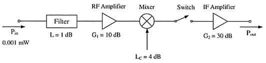
7.3 Swith: ON-state attenuation = 1dB, OFF-state isolation = 40dB. Find the
Pout when a) the switch is ON and b) the switch is OFF.
------------------------------------------------------------------------------------------------------------------
Week-06: Ch04 Components(1)
Lecture 06-1: Directional coupler basics
Problem 6.1 How many ports are there in a
directional coupler?
Lecture 06-2: Directional
coupler in an SWR meter
Problem
6.2 What is a dual directional coupler?
Lecture 06-3: Microwave
components example, 24GHz Doppler radar module
Problem
6.3 Name the components used in the 24GHz Doppler radar in Lecture 06-3.
Lecture notes: Chang chapter 4 (text, slid0es)
------------------------------------------------------------------------------------------------------------------
Week-05: Ch03 Antenna systems(2)
Lecture 05-1: Antenna polarization
Vertical
polarization, Hoizontal
polarization, Circular
polarization, Cross polarization,
Microstrip antenna
circular polarization
Antenna cross polarization
loss
Problem 5.1 What is the circular
polarization?
(공부자료) Antenna
polarization
Lecture 05-2: MIMO antenna technology
MIMO in wireless sysrtems,
What is MIMO?, Dual-band WiFi MIMO antenna
design
Problem 5.2 What is the MIMO antenna
technology?
(공부자료) MIMO
antenna basics 1, MIMO antenna basics
2
Lecture 05-3: Antenna arrays
Antenna arrays, Phased-array simulation for
5G
Problem 5.3 What is the phased array
antenna
(공부자료) Antenna array
------------------------------------------------------------------------------------------------------------------
Week-04: Ch03 Antenna systems(1)
Lecture 04-1:
Antenna gain, https://www.youtube.com/watch?v=NgWSLKcPJ6o
RF and antenna basics, https://www.youtube.com/watch?v=tyr_u8Zfw2U
4.1 Convert 17 dBm power into mW?
(Answer) 17 dBm = 1017/10
mW =
Lecture 04-2: Friis equation, https://www.youtube.com/watch?v=_FWgvvoPmQQ
(Problem) 4.2 With Gt = 20 dB (linear 100), Gr = 10 dB (linear),
frequency = 1 GHz, distance r = PIN
(m), Pt = 10
dBm (10 mW), find the received power.
Lecture 04-3: Helical antenna, https://www.youtube.com/watch?v=QU14gDUNlG4
(Problem) 4.4 With λ = PIN (m), design a six-turn helical
antenna and find its Zin, G, and HPBW.
Lecture
04-4: Yagi antenna, https://www.youtube.com/watch?v=M-9FT5HxSBI
(Problem) 4.4 With f0 = PIN (MHz), design a
three-element Yagi antenna with a folded dipole driver.
Lecture 04-5: Loop antenna, https://www.youtube.com/watch?v=HpoOPdelP8Q
(Problem) 4.5 With f0 = PIN (MHz), design a
full-wave loop antenn. What is its input impedance?
----------------------------------------------------------------------------------------------------------------------
Week-03:
Ch02
Transmission lines and impedance matching (2) (과제
해당 주
일요일 24:00까지)
Lecure 03-1: S parameters, https://www.youtube.com/watch?v=inH_BYQ6feM&t=2s
(Homework)
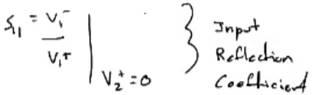
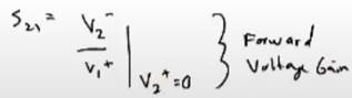
3.1
Define S11 and S21 of a two-port network.
(Answer)
Lecture 03-2: Smith chart, https://www.youtube.com/watch?v=CMBZmiAqRTM
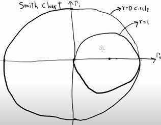
(Homework)
3.2 Draw the r =1 circle on
the Smith chart.
Lecture
03-3: Impedance matching, https://www.youtube.com/watch?v=C1gLdVxwsZg
(Homework)
3.3
What is the impedance matching?
(Answer)
Transforming of the load impedance into the characteristic impedance of the
transmission line
3.4
List three methods of the impedance matching.
(Answer)
1) Impedance
matching with series and parallel lumped elements
2) Impedance
matching with series or parallel stubs
3) Impedance
matching with a quarter-wave transformer
---------------------------------------------------------------------------------------------------------------------
숙제 제출: 3/29 일 24:00까지 (강의청취하면 바로 풀을 수 있음)
Week-02: Ch02 Transmission lines and impedance matching
(1)
Video Lecture: Transmission Lines, https://www.youtube.com/watch?v=sVBFdYgBre4
(Homework)
2.1 A transmission line (전송선) has a length L. On what
condition can it be treated as a lumped-element circuit (집중소자 회로)?
(Answer) L is much smaller than the wavelength.
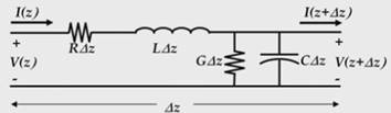
2.2 Draw an lumped-element equivalent circuit (등가회로) of a short section of a transmission line.
(Answer)
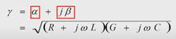
2.3 Write down the formulas for the complex
propagation contant γ (복소전파상수) and the characteristic impeance Z0
(특성임피던스).
(Answer)
Complex propagation constant:
Characteristic impedance Z0:
![]()
2.4 Write down the formulas for the reflection
coefficient (반사계수) in terms of ZL
(부하임피던스) and Z0
(특성임피던스).
(Answer)
![]()
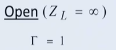
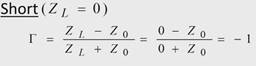
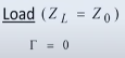
2.5 Write down the reflection coefficient Гo of an open circuit, Гs of a short circuit, and Гm of a (matched) load.
(Answer)
(참고) 상세 한국어 강의영상, https://www.youtube.com/watch?v=LwDye_H0eco&t=1384s
-----------------------------------------------------------------------------------------------------------------------
Week-01:
Ch01 Introduction (코로나19로 원격수업)
Video
lecture: Maxim Integrated, "Fundamentlas of RF and Wireless
Communications", https://www.youtube.com/watch?v=pSDTyUh9cLo
Do the homework
after watching the video lecture.
Homework:
1.1
Explain the operation of OOK modulation.
(Answer) AM
modulation with RF signal on when the modulating digital signal is 1 (high) and
RF signal off when 0.
1.2
Explain the Fourier transformation of a signal?
(Answer) When
a signal is Fourier-transformed, the amplitude and phase of the signal is
obtained versus the frequency.
1.3 What
is the difference between a half-duplex system and a full-duplex system. Give
an example of a full-dulex system.
(Answer)
Half-duplex
system: Transmission and reception not at the same time but at different times.
Full-duplex
system: Transmission and reception at the same time.
Example of
a full-duplex system: Telephone (mobile cellular phone or home wired phone)
1.4 What
do the following acronyms stand for? (spell out each acronym)
a) LNA (low noise
amplifier)
b) PLL (phased locked
loop)
c) PA (power amplifier)
d) PD (phase detector)
e) VCO (voltage
controlled oscillator)
f) VGA (variable gain
amplifier)
g) OSC (oscillator)
1.5 What
is the channel spacing?
(Answer)
Frequency separation between communication channels used to avoid interference
between adjacent channels.
1.6 What
is the definition of ACPR?
(Answer)
ACPR (adjacent channel power ratio): The ratio of the average power in the
adjacent frequency channel to the average power in the transmitted frequency
channel)
1.7 What
is the definition of SNR?
(Answer)
SNR (signal to noise ratio): The radio of the signal power to the noise power
1.8 What
is the definition of NF?
(Answer)
NF (noise figure): The ratio of the signal-to-noise ratio (SNR) at the output
to the SNR at the input
1.9 What
is the difference between the bit rate and the symbol rate?
(Answer)
Bit rate: The number of
digital signal bits transmitted per second
Symbol rate: The number
of symbols (a symbol is a ground of bits) transmitted per second
1.10 What
is the definition of BER?
(Answer)
The ratio of bits in error to the total number of bits received
1.11 What
is the defintion of P1dB?
(Answer)
The output power level at which the gain decreases 1dB from its constant gain
value
References:
Textbook:
Chang, "Chapter
1 Introduction"
Slide:
Cho, "Microwave
Systems"
--------------------------------------------------------------------------------------------------------------
Week-02: Ch02 Transmission lines and impedance matching
Week-03: Ch02 Transmission lines and impedance matching
Week-04: Ch03 Antenna systems
Week-05: Ch03 Antenna systems, Exam 1
Week-06: Ch04 Components 1
Week-07: Ch04 Components 2, 전반부 예제 및 풀이
Week-08: Mid-term exam
Week-09: Ch05 Receivers
Week-10: Ch06 Transmitters, Exam 2
Week-11: Ch06 Transmitters
Week-12: Ch07 Radars
Week-13: Ch07 Radars
Week-14: Ch08 Wireless communication systems
Week-15: Ch08 Wireless communication systems, Exam 3, Final
exam