Qualifying Exam Sample Problems
RF시스템, 고급전자기학I, 고급전자기학II, 능동초고주파회로, 마이크로파CAD및측정, 생체의료용전자파, 수동초고주파회로, 안테나공학, 전파관리특론, 전파공학실험, 전파신호계측, 전파통신특강I, 초고주파통신시스템설계
23: 고급전자기학2(서,류), 전기자기센서(서,류), 안테나측정(서), 전파신호계측(류)
[RF시스템
Problem set 1
1. Write the formula for the Doppler
frequency. Find the Doppler frequency due to a target moving at 10 m/s toward
the source whose frequency is 24 GHz.
2. Explain the noise bandwidth of a receiver.
Calculate the thermal noise power at 290 K in a receiver with a bandwidth of 1
MHz.
3. Tx antenna gain = 30 dB, Rx antenna gain =
30 dB, Tx-Rx separation = 10 km, frequency = 1 GHz, Tx power = 10 dBm. Find the
received power in dBm.
4. A signal with S/N = 20 dB is passed
through an 20-dB gain amplifier with noise figure of 4 dB. Find the S/N at the
output of the amplifier.
Problem set 2
Amplifier
1: gain = 20 dB, noise figure = 1 dB
Amplifier
2: gain = 20 dB, noise figure = 6 dB
A signal
of -80 dBm is applied to the input of Amp 1. The output of Amp 1 is applied to
the input of Amp 2. The output of the Amp 2 is applied to a mixer with
conversion loss of 5 dB.
The signal
also contains noise whose power is -100 dBm.
1. Find
the signal power at the output of Amp 2.
2. Find
the noise power at the output of Amp 2.
3. Find
the signal power at the output of the mixer.
4. Find
the noise power at the output of the mixer.
[고급전자기학 I]
Problem set 1 (25 points for each problem)
1. Give the Maxwell equations in a
differential form.
2. Give the boundary conditions an interface
between two dielectric materials.
3. Give the formula for the skin depth in a
conductive material and provide the physical meaning of the skin depth.
4. Find the high-frequency resistance of a
conductor with conductivity σ of
radius R and length L.
Problem set 2 (25 points for each problem)
1. Write down the boundary conditions for the
electric and magnetic fields on the surface of a perfect electric conductor.
2. The electric field of a planewave is x-directed and has a magnitude of
0.1V/m. Find the direction and magnitude of the magnetic field.
3. There is two inductors (Inductor 1 and
Inductor 2) coupled to each other. Express the terminal voltage of each
inductor in terms of terminal currents, self and mutual inductances.
4. Show that the mutual inductance in Problem
3 can be found by the open and short circuit method.
Problem set 3 (25 points for each problem) Solutions
1. Write down the boundary conditions for
time-varying electric and magnetic fields on a dielectric interface.
2. A planewave with power density of 0.0001
W/m2 is given. Find its rms electric field E (V/m) and rms magnetic field H
(A/m)
3. Explain the concept of magnetic induction.
4. A planewave is incident with zero
incidence angle upon a dielectric surface with ![]() from air. Find
the reflection coefficient
from air. Find
the reflection coefficient ![]() and the transmission
coefficient T.
and the transmission
coefficient T.
Problem set 4 (25 points for each problem) Solutions
1. Write down the boundary conditions in
vacuum for time-varying electric and magnetic fields on a perfect electric
conductor.
2. The electric field of a plane wave in
vacuum is given by
Ex = 10 exp(−0.2πz) (V/m), Ey = 0, Ez
= 0
1) Find the magnetic
field: Hx, Hy, Hz
2) Find the power
density.
3) Find the
propagation constant.
4) Find the
wavelength.
5) Find the
frequency.
3. An infinite
filament current at (x, y, z)
= (0, 0, z) of I = 1A flows in the positive z
direction. Find the magnetic field H at (x, y, z) = (1, 0, 0).
4. The xy-plane is electrically charged with a
uniform density of 1 nC/m2. Find the electric field E at (x, y,
z) = (1, 1, 1).
[고급전자기학 II]
Problem Set 1:
1. Write down the boundary conditions on the
surface of
a) a perfect electric conductor and
b) a perfect magnetic conductor.
2. A planewave in vacuum has power density of
1 W/m2. Find
a) the electric field E (V/m)
and
b) the magnetic field H (A/m)
of the planewave.
3. The mutual inductance L21 between Inductor 1 and Inductor 2 is 1 μH. A voltage of 10cos(10t+π)
is applied to the terminals of Inductor 1. Find the voltage induced on the
terminals of Inductor 2.
4. Design a 1n-F capacitor using a section of
a coaxial cable.
Problem Set 2:
1. Explain
the relation between V (electric scalar potential) and E (electric field
vector).
2. Explain
the complex dielectric constant.
3. Describe
the relation between E, H, k in a planewave.
4. Describe
the difference between static electric and magnetic fields and time-varying
electromangetic fields.
Problem Set 3:
1. Write down the Maxwell's equations
2. Explain the Faraday's law of magnetic induction.
3. Explain the Gauss's law in electrostatics
4. Explain the Ampere's law in magnetostatics
Problem Set 4:
1. Explane the intrinsic impedance of a planewave.
Calculate the intrinsic impedance of a planewave in a medium with er = 4 and ur
= 9.
2. State the boundary conditions for a time-varying
electric and magnetic fields on a perfect conductor.
3. Find the reflection coefficient of a planewave
normally incident from air (er=1) to water (er=81).
4. Find the magnetic field inside a coaxial cable
with a = 1mm, b = 4mm, er=4, ur=1.
Problem Set 5:
1. Write down the boundary conditions for the
electric field E and magnetic field H on the surface of
a) a perfect electric conductor in air
b) a perfect magnetic conductor in air
2. Planewave electric field in air is given
by
E = 377ax
exp(-j2πz) (V/m)
a) Find the magnetic field vector H
(A/m).
b) Find the wavelength λ (m).
c) Find the frequency f (Hz).
3. Planewave is incident normal to a material
boundary as shown in the figure below.
Region 1: εr
= 1.0, μr = 1.0
Region 2: εr
= 4.0, μr = 1.0
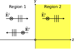
Ei = 377ax exp(-j2πz) (V/m)
a) Find Et
b) Find Er
4. In Problem 3, find
a) Hi
b) Ht
c) Hr
[능동초고주파회로]
Problem set 1
1. Draw a block
diagram of a super heterodyne receiver.
2. Define a noise
figure of an amplifier and give its physical meaning.
3. Define a conversion
loss of a mixer and give its physical meaning.
4. What is a TCXO?
What is its typical stability.
Problem set 2
Amplifier 1: gain =
20 dB, noise figure = 1 dB
Amplifier 2: gain =
30 dB, noise figure = 3 dB
A signal of -80 dBm
is applied to the input of Amp 1. The output of Amp 1 is applied to the input
of Amp 2. The output of the Amp 2 is applied to a mixer with conversion loss of
5 dB.
The signal also
contains noise whose power is -100 dBm.
1. Find the signal
power at the output of Amp 2.
2. Find the noise
power at the output of Amp 2.
3. Find the signal
power at the output of the mixer.
4. Find the noise
power at the output of the mixer.
[마이크로파 CAD 및 측정]
Problem set 1
1. Explain the physical meaning of the
scattering matrix of a 2-port device.
2. Describe how to measure S11, S21 of a
2-port device.
3. Give the block diagram of a 2-port vector
network analyzer.
4. Give the theory for the 1-port calibration
with SOLT (short, open, load termination) method.
Problem set 2
1. Draw a signal flow graph for a two-port
devices specified by a scattering matrix.
2. Port 2 of a two-port device is terminated
with ZL. The
characteristic impedance of port 1 is Z0.
Find the input impedance at port 1.
3. Draw a block diagram of a spectrum
analyzer.
4. We want to analyze a microstrip circuit
using CST Studio Suite. Give a guideline for the size of the wave port to be
set up at the input of the microstrip line.
Problem set 3 Solutions
1. Draw a block diagram of a two-port vector
network analyzer.
2. The scattering parameters of a two-port
device are given by ![]() . Find the fraction of power dissipated in the device
relative to the power incident upon port 1.
. Find the fraction of power dissipated in the device
relative to the power incident upon port 1.
3. Draw the structure of a microstrip
quadrature hybrid coupler.
4. Write down the scattering matrix of an
ideal quadrature hybrid coupler.
[생체의료용전자파]
Problems set 1
1. Describe ISM frequency bands and use of
them in medical devices.
2. What is the SAR (specific absorption
rate)?
3. Give a short description of the theory of
computed tomography.
4. Give a typical dielectric constant and
loss tangent of a human muscle tissue and find the skin depth at 2.45GHz.
Problems set 2
1. A biological tissue has dielectric
constant of 10 and loss tangent of 0.5. Find the skin depth of planewave at
2.4GHz.
2. Explain the radio frequency ablation.
3. Explain the microwave hyperthermia.
4. What is the SAR limit
(in Korea) for general public to radio frequency irradiation?
[수동초고주파회로]
Problem set 1
1. A load impedance 20+j20 (ohm) is connected at the end of a transmission line with
characteristic impedance 50 ohms. Find the reflection coefficient at the load.
Find the radio of the load power to the incident power.
2. Draw a diagram of a quadrature hybrid
coupler and give its scattering matrix.
3. Draw a Wilkinson power divider and give
its scattering matrix.
4. Draw a conceptual diagram of a 10-dB
coupled-line directional coupler and give its scattering matrix.
Problem set 2
1. Draw a diagram of a ring hybrid coupler.
(30 points)
2. Draw a 1:1 T-junction power with input
line impedance of 50 ohms. (30 points)
3. Explain the meaning of the scattering parameters
S11, S21, S12, S22 of a two-port network. (40 points)
Problem set 3
1. Draw the
structure of a ring hybrid coupler and present its scattering matrix.
2. Explain
the cutoff in the TE10 mode in a rectangular waveguide.
3. Explain
the electric and magnetic field distributions in a coaxial cable. Explain the
difference between wave impedance and characteristic impedance in a coaxial
cable.
4. Draw the
structure of the Wilkinso power divider and give its scattering matrix.
[안테나공학]
Problem set 1
1. For a short dipole, draw the E-plane gain
pattern and the H-plane gain pattern.
2. Draw a prime-focus parabolic reflector and
explain the theory of operation.
3. Give a formula for the far field distance
of an antenna and explain the physical meaning of the far-field distance of an
antenna
4. Form an RHCP antenna using a ground plane,
and two dipoles.
Problem set 2
1. Draw the structure of a rectangular patch
antenna including the feeding structure.
2. Draw the structure of an RHCP helical
antenna. Given its diameter D, find the operating frequency of the helical
antenna in terms of wavelength
3. Design a two-element array of parallel
dipoles with quarter-wave spacing with the maximum gain in the direction
perpendicular to the dipole arm.
4. Construct an LHCP antenna consisting of
two dipoles above a PEC ground plane.
Problem set 3
1. Draw the structure of a center-fed
half-wave dipole antenna on the z axis. Draw the current distribution on
a half-wave dipole antenna. Draw the E-plane gain pattern of a half-wave
dipole antenna.
2. Explain the directivity of an antenna.
Explain the relation of the antenna directivity with the antenna gain.
3. An antenna is fed by a transmission line
with characteristic impedance of 50 ohms. The antenna's input impedance is 150
ohms. Find the input reflection coefficient of the antenna. Find the impedance
match efficiency.
4. Draw a vertically-polarized half-wave
dipole antenna and a horizontally-polarized half-wave dipole antenna. Find the polarization
efficiency between two antennas.
Problem set 4:
Antenna Tx power 1 W, frequency 1 GHz,
distance 3 km, antenna gain 20 dB.
1. Find the power density (W/m2).
2. Find the electric field
strength (V/m).
3. Find the magnetic field
strength (A/m).
5. Received power with a 20-dB
gain receiving antenna (dBm).
[안테나측정
Problem Set 1:
1.
Write down the Friis transmission equation. Make an example for numerical
calculation.
2.
Write down the 7 steps in antenna developments.
3.
Explain the
reflection coefficient and the transmission coefficient of a two-port device.
4. Give the signal flow graph representation
of a two-port device.
Problem Set 2: Solutions
1. We will measure two antenna interaction
using the scattering parameters S11, S12, S21, and S22. Define S11, S12, S21,
and S22.
2. Explain how to measure the axial ratio of
a circularly polarized antenna using a rotating dipole antenna.
3. Regarding the far-field region of an
antenna
1) Write down the miniumu distance from an antenna
to the beginning of the far-field region.
2) Explain the physical reason behind the
far-field region.
3) Describe the characteristics of the
far-field region in the perspective of antenna gain measurement.
4. Explain the principles of the antenna gain
measurement using a reference antenn and an antenna under test.
[적응빔형성 배열안테나]
Problem set 1 Solutions
For a uniformly spaced N-element linear array,
1. Draw the array geometry including the
coordinate axis
2. Write an expression for the array factor
3. A collinear small dipole is used as the
array element. Write the element factor.
4. Write the total pattern factor.
5. For N
= 6, determine the maximum element spacing such that no part of the grating
lobe appears in the visible region. The array boresight is normal to the array
axis.
6. For N
= 6, determine the maximum element spacing such that no part of the grating
lobe appears in the visible region. The array boresight is 45 degrees away from
the direction normal to the array axis.
7. The array is placed at a distance h from an infinite PEC ground plane.
Find an optimum h which is less than
a wavelength.
8. Now make the dipole axis normal to the
array axis and repeat 7.
9. Find the inter-element phase shift for the
array in Problem 6.
10. Qualitatively plot the E-plane pattern of
the array in Problem 6.
Problem set
For a uniformly spaced N-element linear array,
1. Draw the array geometry
including the coordinate axis
2. Write an expression for the
array factor
For a uniformly spaced M by N
element planar array,
3. Draw the array geometry
including the coordinate axis.
4. Write an expression for the
array factor.
3. A collinear small dipole is used as the
array element. Write the element factor.
4. Write the total pattern factor.
[전파관리특론]
Problems set 1 Solutions
1. Draw a block diagram of a spectrum
analyzer and provide a theory of operation
2. Discuss the unitization of ISM frequency
bands.
3. Find the electric field strength dBuVrms/m
at a point (P) 100 m in the boresight
direction of and away from a 2-GHz 10-dB gain antenna transmitting 10mW.
4. Find the power received by a 2-GHz 10-dB
polarization-matched antenna at the point P
in Problem 3
Problems set 2
Antenna Tx power 1W, frequency 1.8GHz,
distance 3km, antenna gain 20dB.
1. Find the power density (W/m2).
2. Find the electric field strength (V/m).
3. Find the magnetic field strength (A/m).
5. Received power with a 20-dB gain receiving
antenna (dBm).
[전파공학실험]
Problem set 1 Solutions
1. Draw a block diagram of a microwave
network analyzer and provide a theory of operation
2. Explain the theory of one-port calibration
in a network analyzer measurement.
3. Explain how to measure the mutual coupling
between two antennas using a network analyzer.
4. Explain how to measure the gain of an
antenna using a network analyzer.
Problem set 2
1. Draw a block diagram of an antenna
measurement system.
2. Explain the theory of operation of the
antenna measurement system given in 1.
3. Derive the Friis transmission formula.
4. Explain how to measure the gain of an
antenna using the Friis transmission formula.
Problem set 3 Solutions
1. Explain the reflection coefficient and the
transmission coefficient of a two-port device.
2. Give the signal flow graph representation
of a two-port device.
3. What's the purpose of the calibration in
vector network measurements.
4. Explain the units dBm and dBμV/m.
[전파신호계측
Problem set
1. Write a block diagram of a two-port
network analyzer. Explain the theory of operation.
2. Write a block diagram of a spectrum
analyzer. Explain the theory of operation.
3. Draw a geometry of a microstrip quadrature
hybrid coupler and write down its scattering matrix.
4. Draw a geometry of a microstrip ring
hybrid coupler and write down its scamttering matrix.
[전파신호처리
Problem Set 1: Solutions
1. Draw a block diagram of an RF mixer and
2. Given
VRF(t) = ARF sin(ω1t + φ1)
VLO(t) = ALO sin(ω2t + φ2)
1) find an expression for the IF signal from
an RF mixer and
2) in the IF signal, find the lower sideband
signal and the upper sideband signal
3. Draw a block diagram of an RF spectrum
analyzer.
4. Draw a block digram of a digital radio
receiver.
[전파통신특강 I
Problem Set 1
1. Explain the white thermal noise power
versus the temperature and the receiving bandwidth.
2. Draw a diagram (block, or functional)
diagram of a double-conversion superheterodyne receiver.
3. Explain the function of a mixer in a
heterodyne communication receiver.
4. Explain the function of a front-end LNA in
a heterodyne communication receiver.
Problem Set 2: Solutions
1. Spell out the following acronyms
1) NFC
2) RFID
3) BLE
4) CDMA
5) TDD
2. Write down the maximum transmit power
of three classes of the Bluetooth communication.
3. Write down an equation for the capacity of a communication channel.
4. State five requirements for LPWAN.
[초고주파통신시스템설계]
Problem set 1
1. Explain the white thermal noise power
versus the temperature and the receiving bandwidth.
2. Draw a diagram (block, or functional)
diagram of a double-conversion superheterodyne receiver.
3. Explain the function of a mixer in a
heterodyne communication receiver.
4. Explain the function of a front-end LNA in
a heterodyne communication receiver.
Problems set 2
1. Give the block diagram of a transmitter
part of an RF front-end in a wireless communication system.
2. Give the block diagram of a receiver part
of an RF front-end in a wireless communication system.
3. Two identical 60-GHz antennas of 40dBi
gain are placed in a 1-km line-of-sight patch with their boresights and
polarization matched. The signal trasmitted power is 1W. Find the received
signal power assuming the atmospheric attenuation of 15dB/km.
4. For the case of the problem 3, find the
SNR with the following parameters:
Antenna
noise temperature: 150K
System
noise figure: 8dB
Receiver
bandwidth: 1GHz
Problem set 3
1. Write down
the Friis transmission equation.
2. Calculate
the thermal noise power at 290 K in a receiver with bandwidth of 10 kHz.
3. Describe the
relation between the noise figure and the equivalent noise temperature of a
device.
4. Explain
the reason why a low-noise amplifier is often employed as the first element
after the antenna in a communication receiver.
Problem set 4
1. Write down a block diagram of a CW Doppler
radar.
2. Write down a block diagram of a
superheterodyne receiver.
3. Calculate
the thermal noise power at 290 K in a receiver with bandwidth of 100 kHz.
4. Write down the Friss transmission
equation.
[전자기센서
Problem Set 1:
1.
Draw a Wheatstone bridge circuit for measuring the resistance of a resistor.
Write down an equation for finding the unknown resistance.
2.
Describe the operating principles of the differential inductive displacement
sensor?
3.
Describe the operating principles of the capacitive displacement sensor
consisting of two parallel plates?
4.
Draw a photodiode readout circuit using a transimpedance amplifer.
[ICT융합특론
Problem
Set 1: Solutions
1.
Write down the frequency range in Korea of the following communication
modalities.
1)
BLE
2)
NFC
3)
UHF-RFID
4)
GPS L1
5)
FM broadcasting
2.
Write down some features of the BLE technology.
3.
Write down some applications of the NFC technology.
4.
Explain the concept of the on-device AI.